

Vehicular damper device
Patent Information
- Authority / Receiving Office
- US · United States
- Current Assignee / Owner
- Publication Date
- 2013-09-19
- Estimated Expiration
- Not applicable · inactive patent
Smart Images
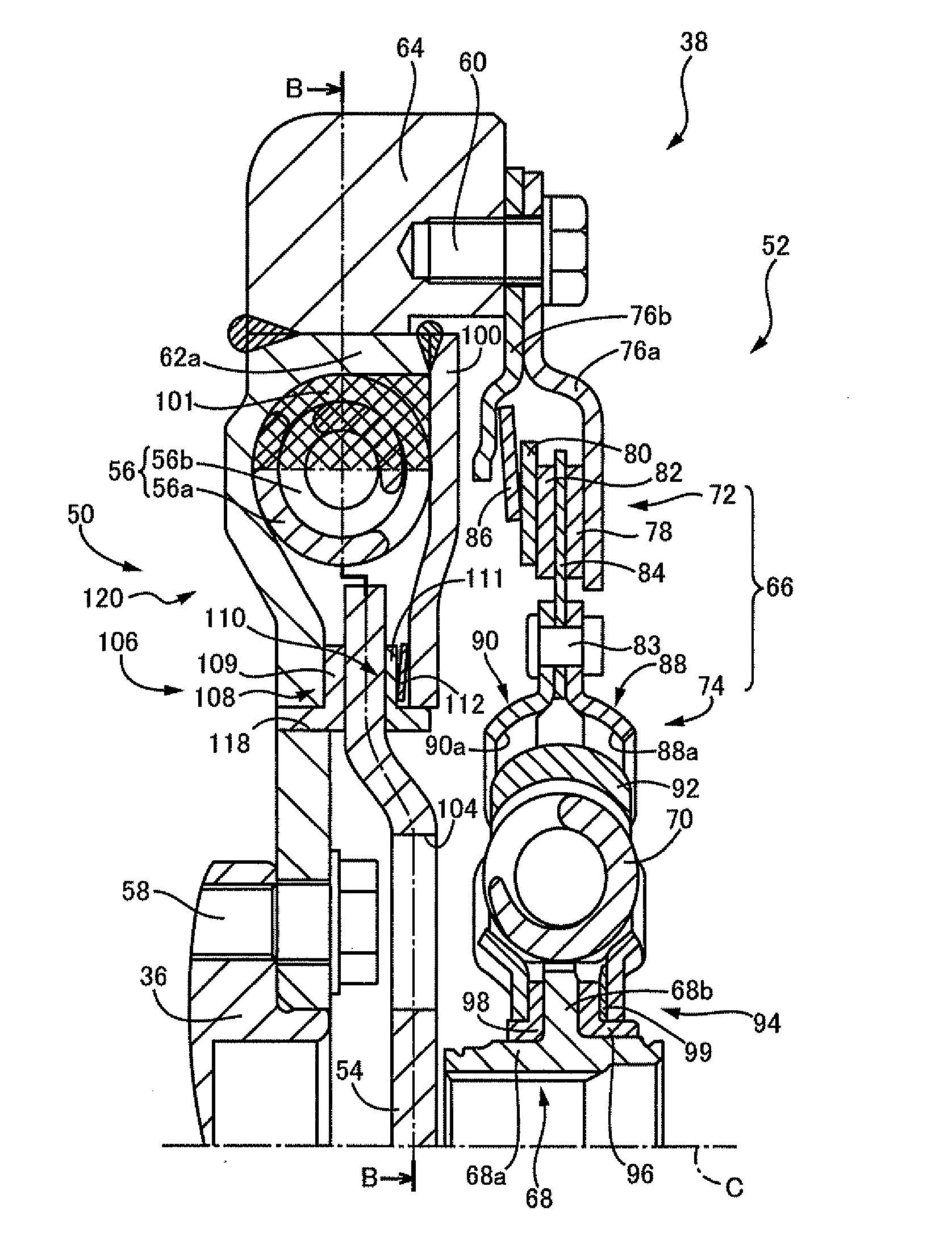
Figure 1 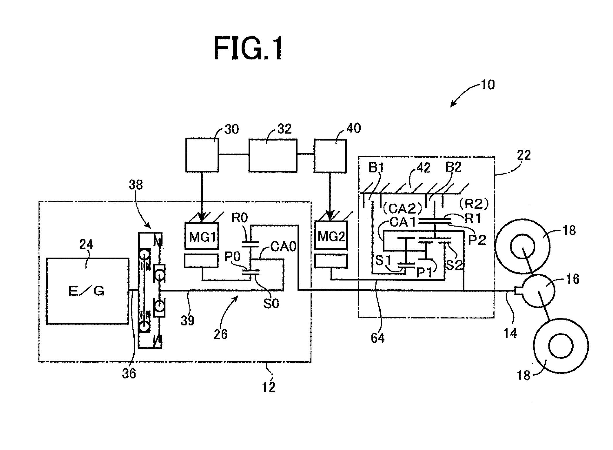
Figure 2 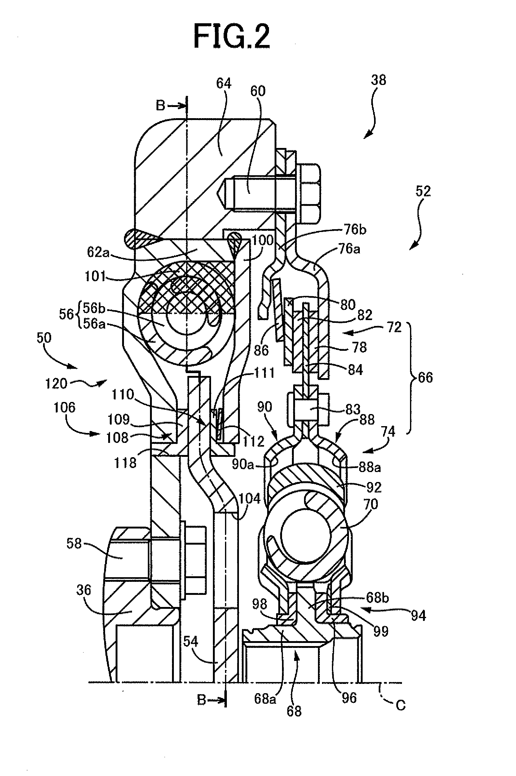
Figure 3
Abstract
Description
TECHNICAL FIELD
[0001] The present invention relates to a vehicular damper device, and more particularly to a construction of a damper capable of achieving a high damping effect.BACKGROUND ART
[0002] There is well known a vehicular damper device which is provided in a power transmitting path between an engine and an output shaft, and which is constructed to restrict transmission of a torsional vibration during power transmission. Patent Document 1 discloses an example of such a vehicular damper device in the form of a dual-mass flywheel. In the dual-mass flywheel 1 disclosed in Patent Document 1, primary flywheel 11 and a secondary flywheel 12 are connected to each other through a torsion spring 13, and the secondary flywheel 12 is provided with a dynamic damper 2 which consists of a mass member 21 and an elastic body 22.
[0003] In the damper device constructed as described above, an inertia mass of the mass member 21 and rigidity of the elastic body 22 are adjusted such that a natural fr...
Examples
embodiment
[0017]FIG. 1 is the schematic view showing the arrangement of a vehicular drive system 10 of a hybrid type to which the present invention is suitably applicable. As shown in FIG. 1, the vehicular drive system 10 is configured such that a torque of a primary drive power source in the form of a first drive power source 12 is transmitted to a wheel drive output shaft 14 functioning as an output member of a vehicle, and is then transmitted from the wheel drive output shaft 14 to a pair of right and left drive wheels 18 through a differential gear device 16. The present vehicular drive system 10 is provided with a second drive power source in the form of a second electric motor MG2 which is operable selectively in a vehicle driving mode for generating a vehicle drive force or a regenerative operation mode for regenerating an electric energy. This second electric motor MG2 is connected to the above-described wheel drive output shaft through an automatic transmission 22. Accordingly, the o...