
Filament Winding Device
a technology of winding device and filament, which is applied in the direction of filament handling, transportation and packaging, thin material processing, etc., can solve the problems of deterioration of production efficiency and production efficiency
Patent Information
- Authority / Receiving Office
- US · United States
- Patent Type
- Applications(United States)
- Current Assignee / Owner
- Publication Date
- 2015-02-19
Smart Images
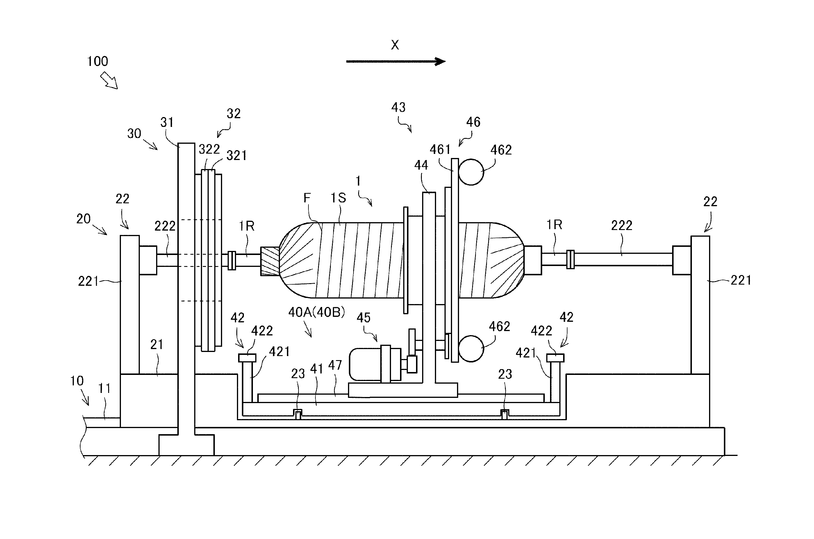
Figure 1 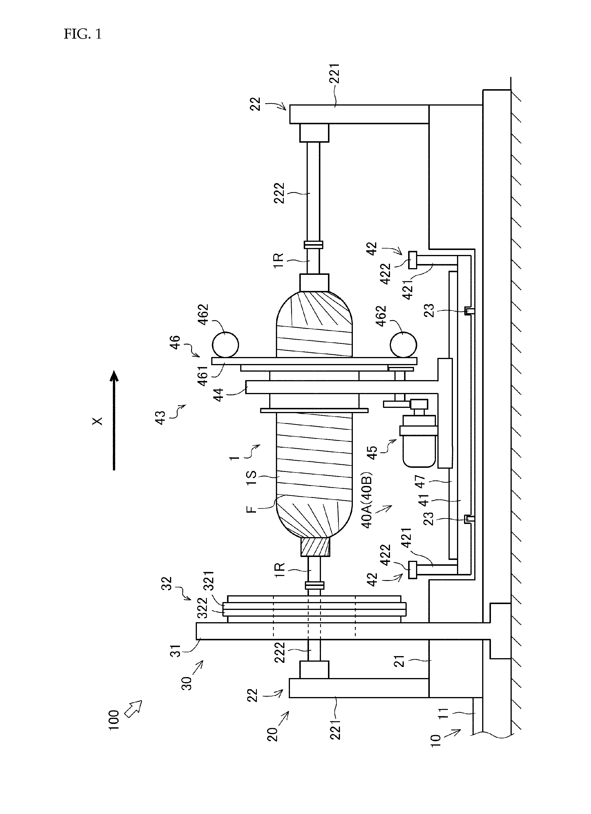
Figure 2 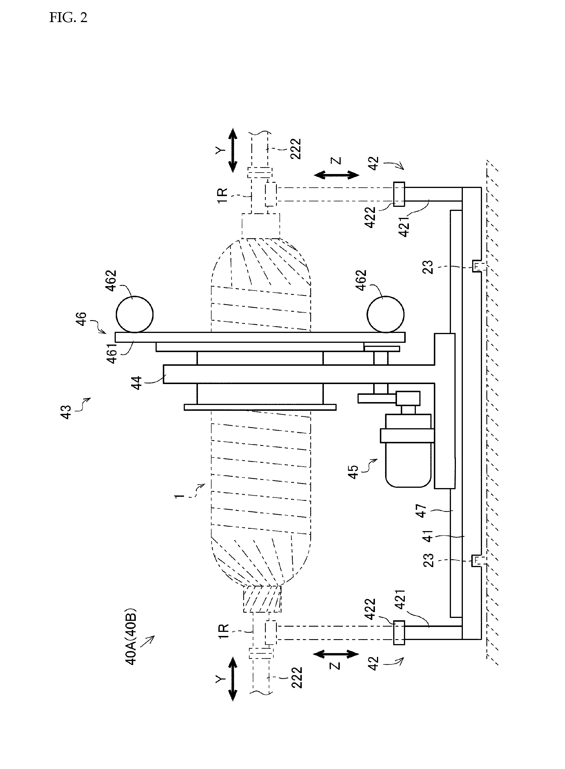
Figure 3
Abstract
Description
TECHNICAL FIELD
[0001] The present invention relates to a technique of a filament winding device.BACKGROUND ART
[0002] Conventionally, a filament winding device which winds a fiber bundle impregnated with resin on to the outer peripheral surface of a liner has been known. The filament winding device is provided with a hoop winding device that winds the fiber bundle on to the outer peripheral surface of the liner by rotating centered around the liner (for example, see Patent Literature 1).
[0003] The hoop winding device is provided with a bobbin in which the fiber bundle has been wound, and the fiber bundle supplied from the bobbin is wound on to the liner by self-rotation of the hoop winding device. As such, with respect to the filament winding including the hoop winding device, when the fiber bundle wound on to the bobbin runs low, there is a need to interrupt the fiber bundle winding operation and exchange the bobbin. However, when the fiber bundle winding operation is interrupted so as...
Examples
Embodiment Construction
[0028]Next, an explanation will be given of embodiments of the present invention.
[0029]First of all, a brief explanation will be given of an overall configuration of a filament winding device 100 (hereinafter, “FW device 100”).
[0030]FIG. 1 is a side view illustrating the overall configuration of the FW device 100. An arrow X in the drawing indicates a transfer direction of a liner 1. The direction in parallel to the transfer direction of the liner 1 is regarded as the longitudinal direction of the FW device 100, and one direction of transferring the liner 1 is defined as the front side (right side in this drawing), and the other direction opposite thereto is defined as the rear side (left side in this drawing). The FW device 100 reciprocates the liner 1 in the longitudinal direction, whereby the front side and the rear side are defined depending on the transfer direction of the liner 1.
[0031]FIG. 2 is a side view illustrating a configuration of trolleys 40A, 40B. An arrow Y in the d...