
Tuning-fork resonator with grooves on principal surfaces
a resonator and principal surface technology, applied in the direction of piezoelectric/electrostrictive/magnetostrictive devices, oscillators, piezoelectric/electrostrictive device details, etc., can solve the problem of generating loss of vibration energy, significantly reducing stiffness of the resonating arm part, and insufficient suppression of heat transfer from the contracting surface to the expanding surfa
Patent Information
- Authority / Receiving Office
- US · United States
- Patent Type
- Applications(United States)
- Current Assignee / Owner
- Publication Date
- 2011-04-07
- Estimated Expiration
- Not applicable · inactive patent
Smart Images
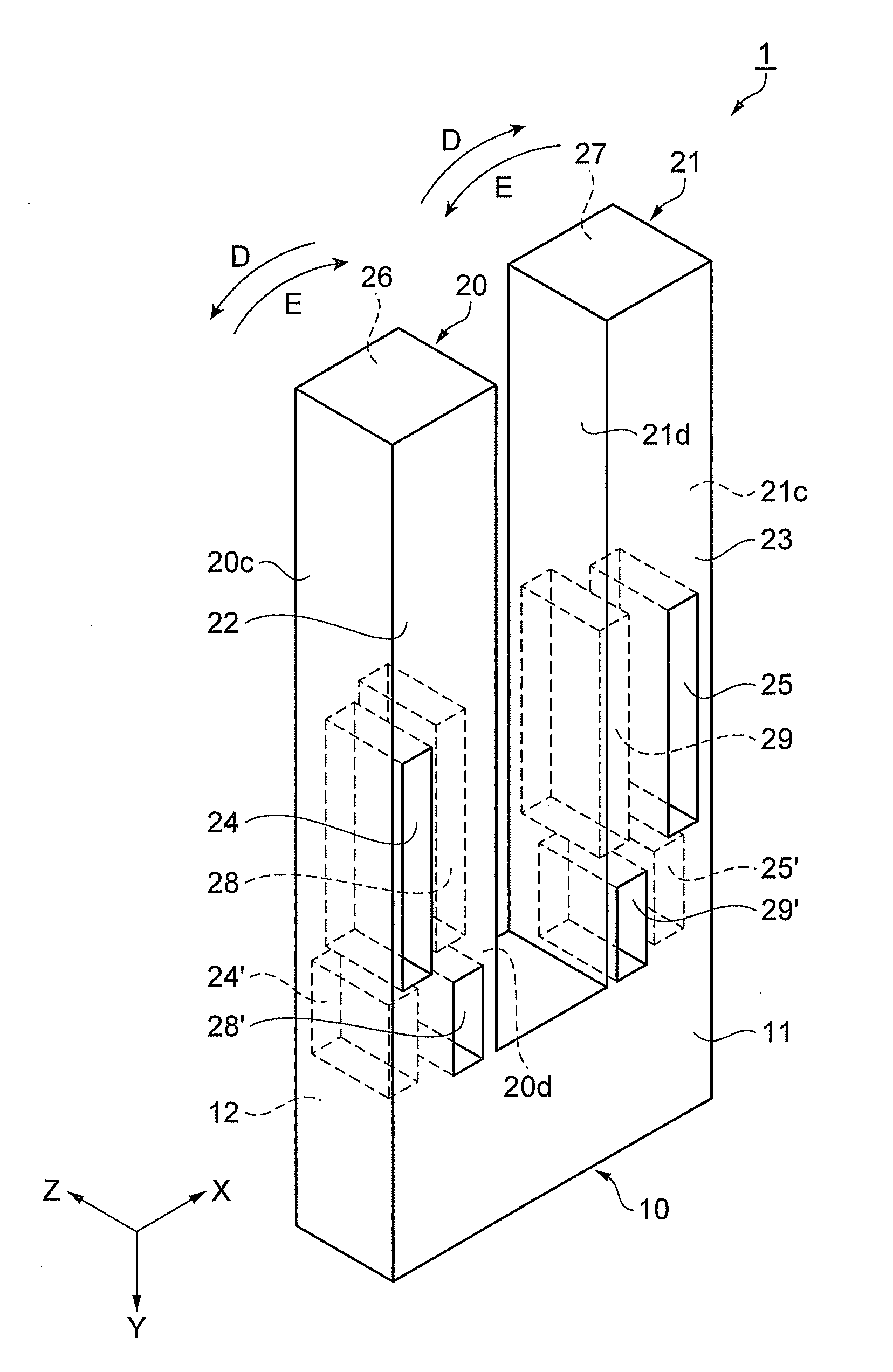
Figure 1 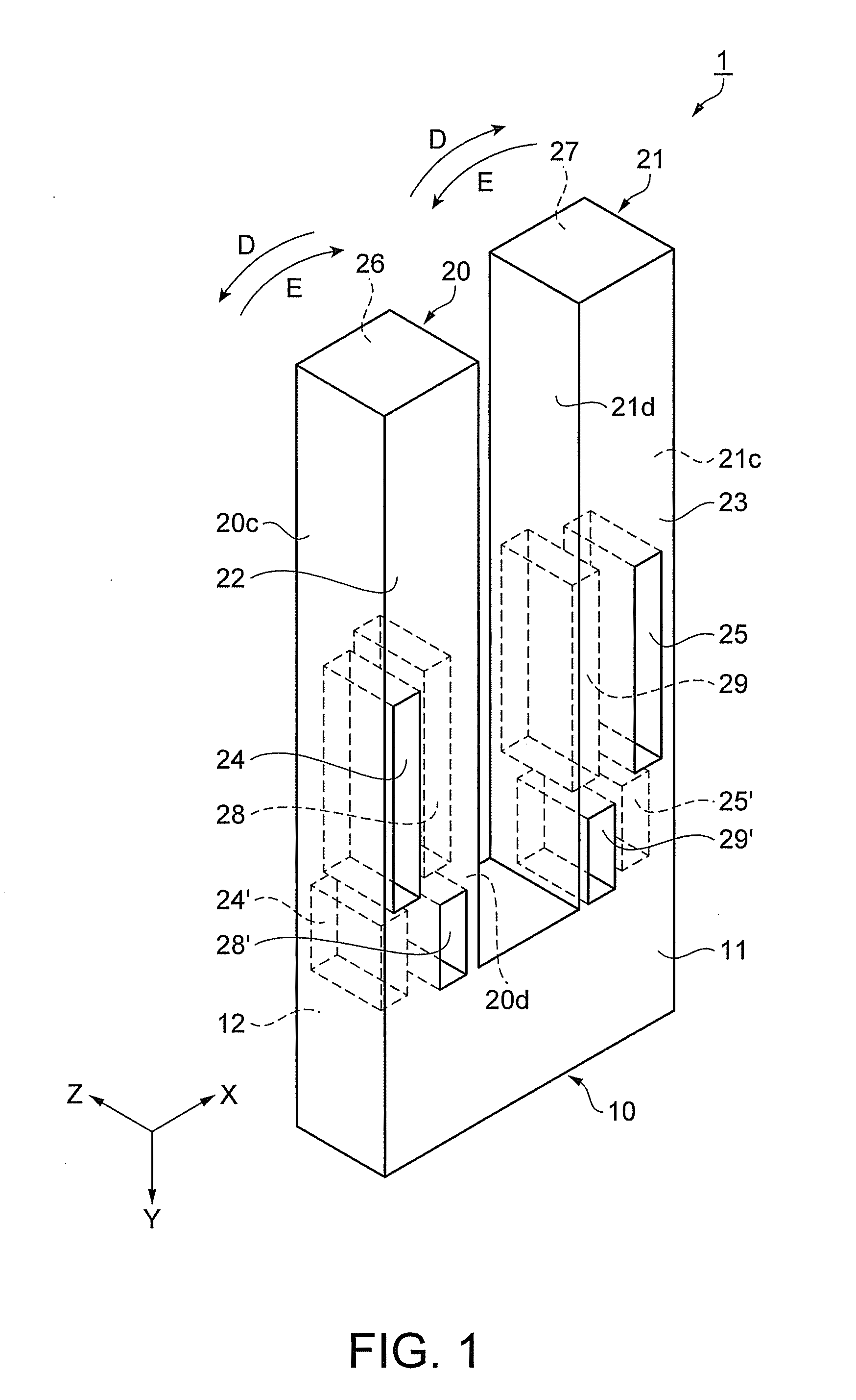
Figure 2 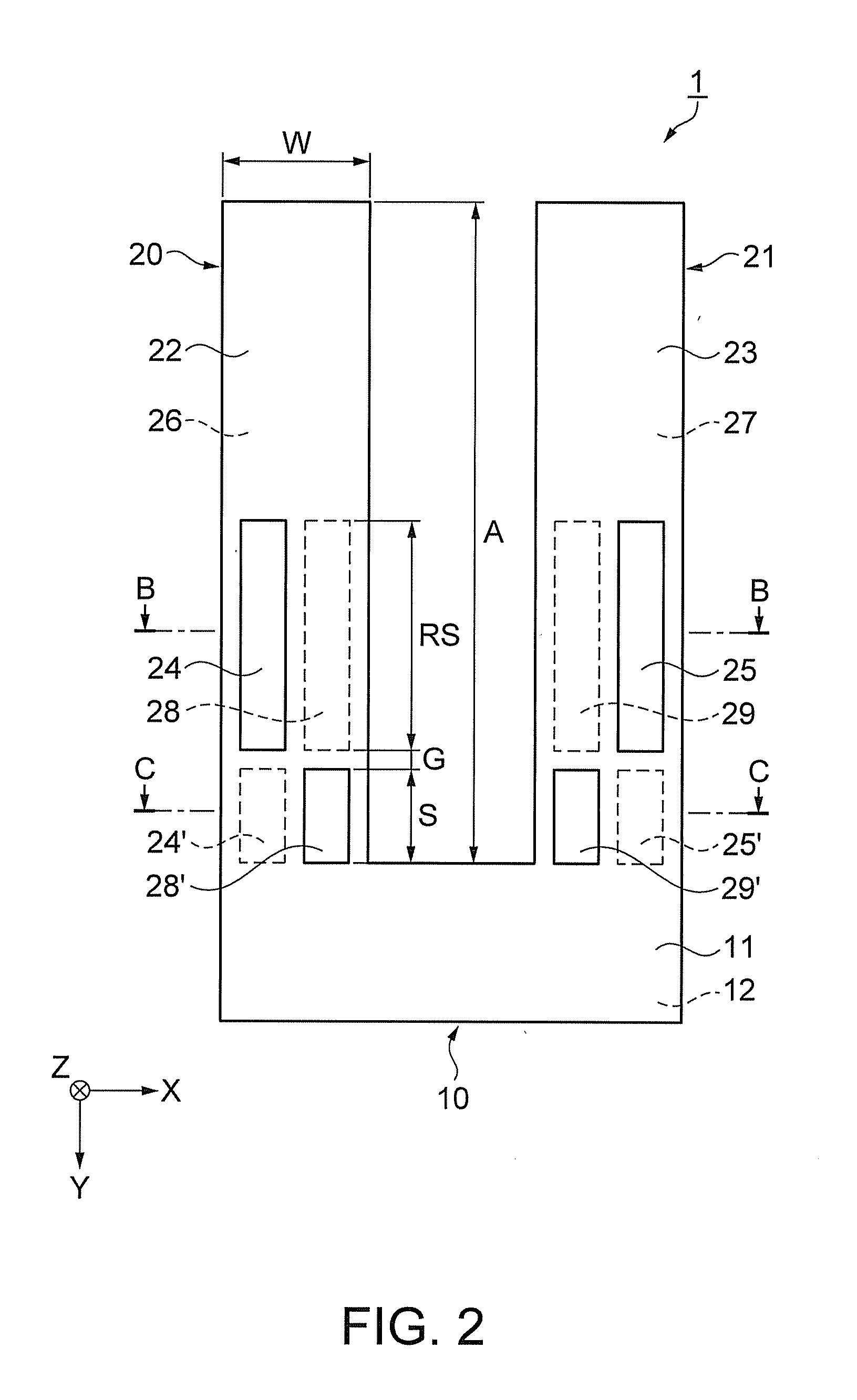
Figure 3
Abstract
Description
BACKGROUND
[0001] 1. Technical Field
[0002] The present invention relates to a resonator element, a resonator, an oscillator, and an electronic apparatus.
[0003] 2. Related Art
[0004] In related art, it is known that, as a piezoelectric resonator element as an example of a resonator element is made smaller, the Q factor becomes smaller and vibration is hindered.
[0005] Specifically, in the piezoelectric resonator element, with elastic deformation due to flexing vibration, the temperature of the contracting surface rises and the temperature of the expanding surface falls, and a temperature difference is produced within. Thereby, in the piezoelectric resonator element, vibration called relaxation oscillation occurs in inverse proportion to a required time (relaxation time) until the temperature difference is eliminated (temperature equilibration) by thermal conduction (heat transfer).
[0006] As the piezoelectric resonator element is made smaller, the frequency of the relaxation oscillation and th...
Examples
first embodiment
[0071]FIG. 1 is a schematic perspective view showing an outline configuration of a quartz resonator element of the first embodiment. FIG. 2 is a schematic plan view of FIG. 1. FIGS. 3A and 3B are schematic sectional views of FIG. 2, and FIG. 3A is a sectional view along B-B line of FIG. 2 and wiring diagram and FIG. 3B is a sectional view along C-C line of FIG. 2 and wiring diagram. Note that, in FIGS. 1 and 2, electrodes and the like are omitted for convenience.
[0072]As shown in FIGS. 1 and 2, a quartz resonator element 1 includes a base part 10, and a pair of resonating arm parts 20, 21 extending from the base part 10 in a first direction (Y-axis direction) and performs flexing vibration.
[0073]The quartz resonator element 1 forms a tuning fork with the base part 10 and the pair of resonating arm parts 20, 21.
[0074]The pair of resonating arm parts 20, 21 are formed in rectangular column shapes, and extend in parallel with each other from one end side of the base part 10 in the Y-ax...
modified example
[0148]As below, a modified example of the quartz resonator element of the first embodiment will be explained.
[0149]FIG. 7 is a schematic plan view showing a quartz resonator element of a modified example of the first embodiment. The same signs are assigned to the common parts with the first embodiment and their explanation will be omitted, and the parts different from those of the first embodiment will be explained mainly.
[0150]As shown in FIG. 7, in a quartz resonator element 101, the arrangement of the first groove part 25 and the second groove part 29 and the third groove part 25′, and the fourth groove part 29′ in a resonating arm part 121 is reversed compared to the arrange of those of the resonating arm part 21 of the quartz resonator element 1 in the embodiment. In other words, in the quartz resonator element 101, the arrangement of the respective groove parts is the same in the resonating arm part 20 and the resonating arm part 121.
[0151]The quartz resonator element 101 may ...
second embodiment
[0153]As below, a quartz resonator as a resonator of the second embodiment will be explained as an example.
[0154]FIG. 8 is a schematic plan view showing an outline configuration of a quartz resonator of the second embodiment. FIG. 9 is a schematic sectional view along J-J line of FIG. 8. In FIG. 8, a lid body is omitted for convenience.
[0155]Further, the same signs are assigned to the common parts with the first embodiment and their explanation will be omitted.
[0156]The quartz resonator 80 of the second embodiment is a quartz resonator using the quartz resonator element of the first embodiment or the modified example of the first embodiment. Here, the explanation will be made using the quartz resonator element 1 of the first embodiment.
[0157]As shown in FIGS. 8, 9, the quartz resonator 80 houses the quartz resonator element 1 within a package 51. Specifically, the quartz resonator 80 houses the quartz resonator element 1 in an internal space S of the package 51 including a first sub...