
Stator and rotating electric machine
Patent Information
- Authority / Receiving Office
- US · United States
- Current Assignee / Owner
- Publication Date
- 2015-11-12
Smart Images
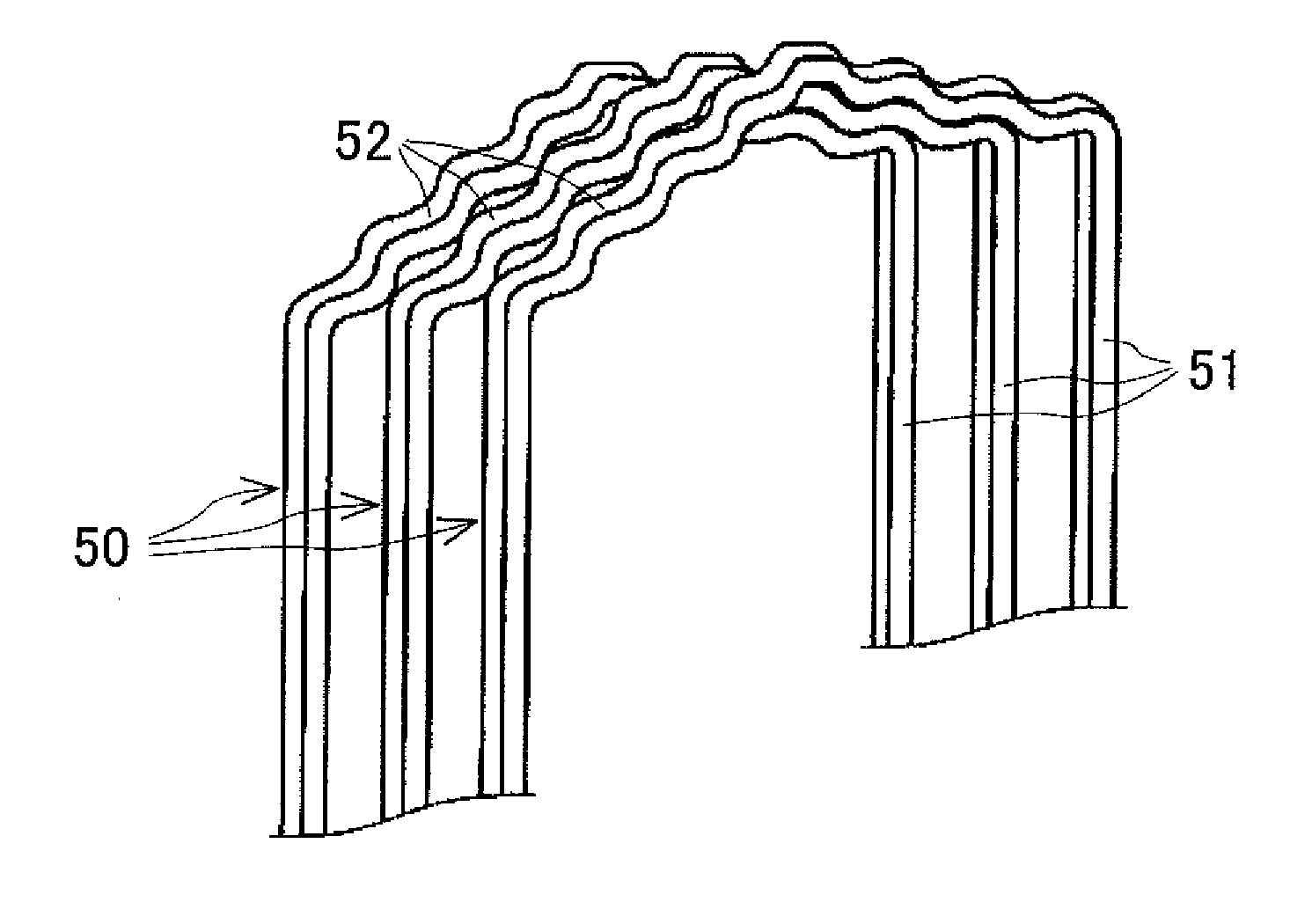
Figure 1 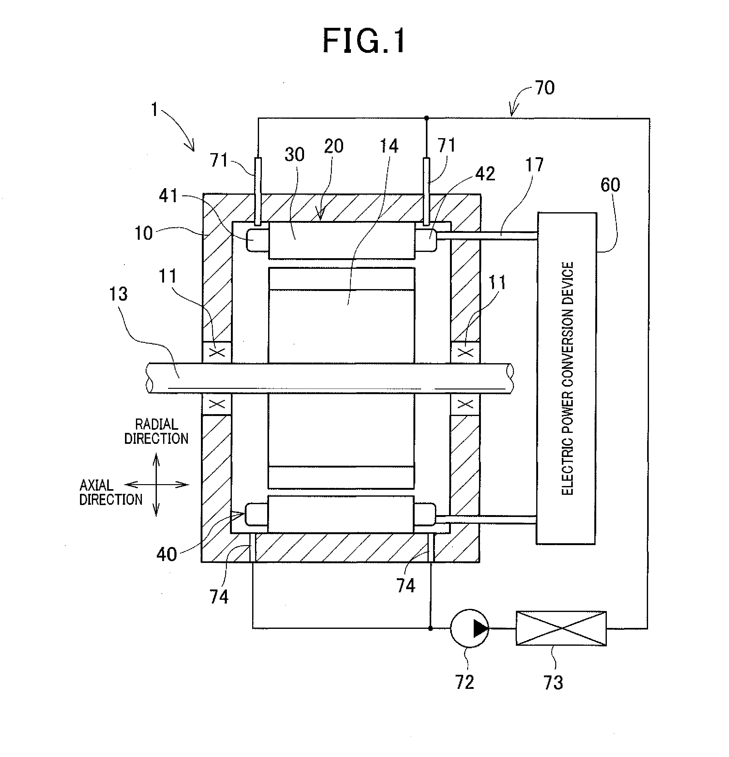
Figure 2 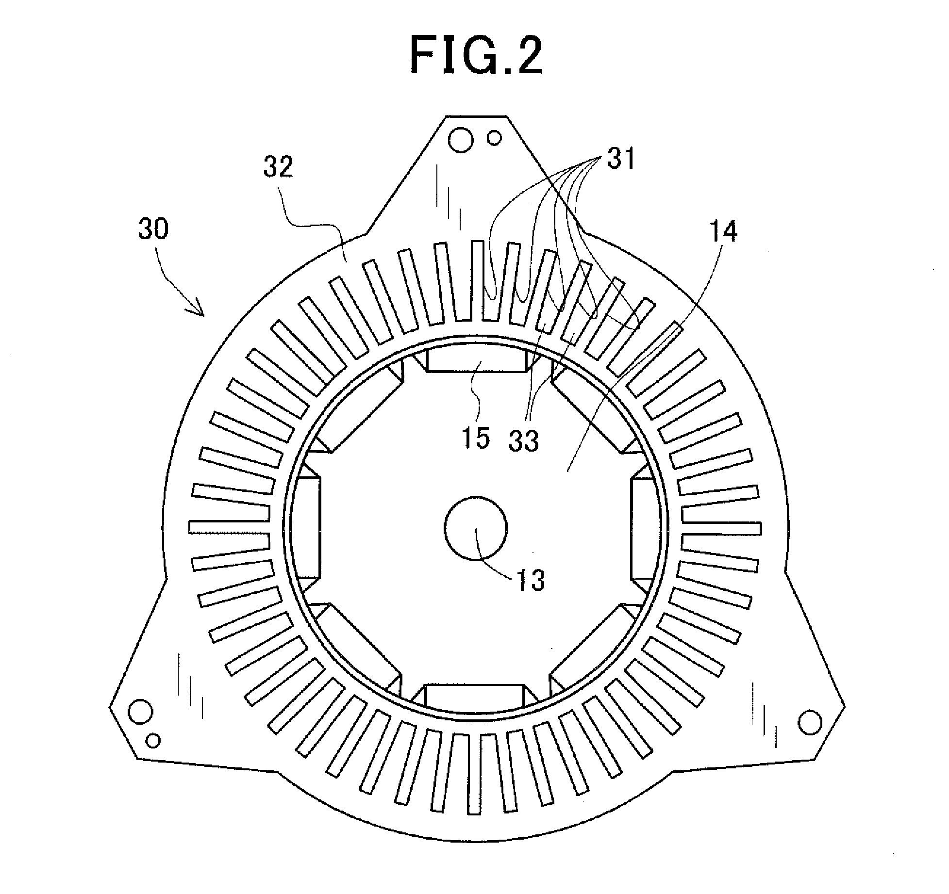
Figure 3
Abstract
Description
CROSS-REFERENCE TO RELATED APPLICATION
[0001] This application is based on and claims priority from Japanese Patent Application No. 2014-96807, filed on May 8, 2014, the content of which is hereby incorporated by reference in its entirety into this application.BACKGROUND
[0002] 1 Technical Field The present invention relates to stators and rotating electric machines that include the stators and are used in, for example, motor vehicles as electric motors and electric generators.
[0003] 2 Description of Related Art
[0004] There are known rotating electric machines that are used in, for example, motor vehicles as electric motors and electric generators. Those rotating electric machines generally include a rotor and a stator. The stator includes an annular (or hollow cylindrical) stator core and a stator coil. The stator core is disposed in radial opposition to the rotor and has a plurality of slots that are formed in the stator core so as to be spaced from one another in the circumferential di...
Examples
first embodiment
[0034]FIG. 1 shows the overall configuration of a rotating electric machine 1 according to the first embodiment.
[0035]In the present embodiment, the rotating electric machine 1 is configured as an inner rotor-type motor-generator for use in, for example, a motor vehicle. The motor-generator can selectively function either as an electric motor or as an electric generator.
[0036]As shown in FIG. 1, the rotating electric machine 1 includes a housing 10, a rotating shaft 13, a rotor 14, a stator 20 that includes an annular stator core 30 and a three-phase stator coil 40, and a coolant supplier 70. Moreover, the rotating electric machine 1 is electrically connected with an electric power conversion device 60 via input / output lines 17. The housing 10 of the rotating electric machine 1 and a case member (not shown in the figures) of the electric power conversion device 60 may be either integrally formed into one piece or separately formed and then fixed together by fixing means. The fixing ...
second embodiment
[0081]A stator 120 according to the second embodiment will be described with reference to FIGS. 11-16.
[0082]The stator 120 according to the present embodiment is also designed to be used in the rotating electric machine 1 (see FIG. 1) described in the first embodiment.
[0083]As shown in FIG. 11, the stator 120 includes an annular stator core 130, which is obtained by assembling a plurality of stator core segments 132 divided in its circumferential direction, and a stator coil 140 that is comprised of a plurality of continuous electric wires 150 mounted on the stator core 130.
[0084]Specifically, as shown in FIG. 12, the stator core 130 is comprised of the plurality (e.g., 24 in the present embodiment) of stator core segments 132 that are arranged in the circumferential direction of the stator core 130 so as to adjoin one another in the circumferential direction. On the radially outer surface of the stator core 130 (or the radially outer surfaces of the stator core segments 132), there...