
Repeater
Patent Information
- Authority / Receiving Office
- US · United States
- Current Assignee / Owner
- Publication Date
- 2017-12-21
Smart Images
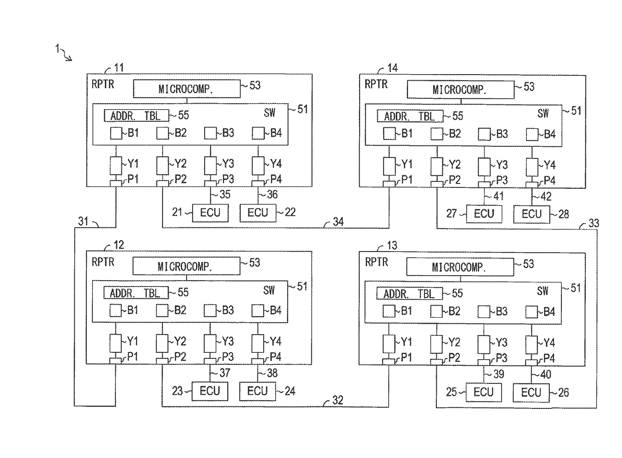
Figure 1 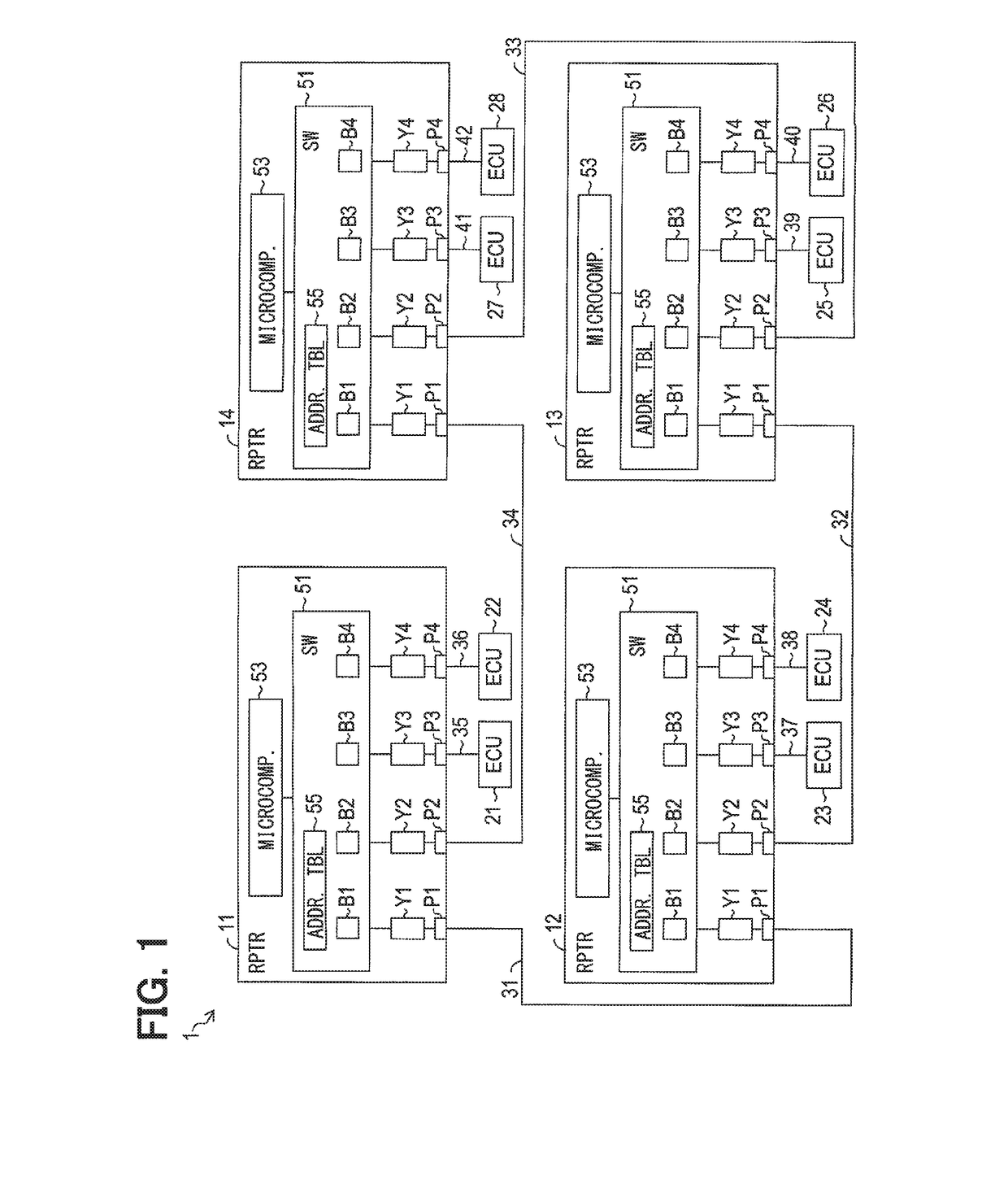
Figure 2 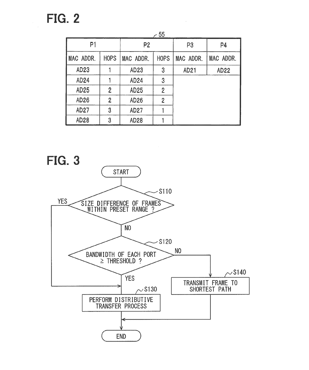
Figure 3
Abstract
Description
CROSS REFERENCE TO RELATED APPLICATION
[0001] The present application is based on and claims the benefit of priority of Japanese Patent Application No. 2016-118914, filed on Jun. 15, 2016, the disclosure of which is incorporated herein by reference.TECHNICAL FIELD
[0002] The present disclosure generally relates to a repeater for organizing a communication network.BACKGROUND INFORMATION
[0003] For example, in a patent document, Japanese Patent Laid-Open No. 2010-509825 (patent document 1), an idea of frame transfer between the nodes via a shortest path in an Ethernet network is disclosed (Ethernet: registered trademark). The shortest path is a shortest communication path in which the number of repeaters through which the frames pass to reach a destination node (i.e., a relay number, or “HOPS”) takes the minimum value.
[0004] In the repeater that adopts the idea of the patent document 1, when frames with the same address are received simultaneously from two or more ports, each of the received...
Examples
first embodiment
1. First Embodiment
[0019][1-1. Configuration]
[0020]A communication network 1 of the first embodiment shown in FIG. 1 is the Ethernet network disposed in, for example, a vehicle, e.g., a passenger vehicle, and serves as a communications system in the vehicle.
[0021]As shown in FIG. 1, the communication network 1 is provided with repeaters 11-14, Electronic Control Units (ECUs) 21-28 respectively serving as a communication node, and communication lines 31-42.
[0022]The repeaters 11-14 are provided with a function to serve as an Ethernet switch to relay communications between the ECUs 21-28.
[0023]Further, the repeaters 11-14 are provided with a plurality of ports for transmitting and receiving frames. The repeaters 11-14 are provided with four ports P1-P4 in the example of the present embodiment. The repeaters 11-14 are provided with a switch part 51, respectively. The switch part 51 performs a relay process for relaying the communications according to the Ethernet standard.
[0024]The rep...
second embodiment
2. Second Embodiment
[0113][2-1. Difference of the Second Embodiment from the First Embodiment]
[0114]The configuration of the second embodiment is basically the same as that of the first embodiment, with a difference discussed below.
[0115]The same numerals are used for the same components / configurations as the first embodiment, thereby not repeating the same descriptions.
[0116][2-1-1. Configuration]
[0117]A communication network 60 of the second embodiment shown in FIG. 4 is provided with repeaters 61-68 and ECUs 71-76. The ECUs 71-75 are connected to the repeater 61. The ECU 76, which may be a destination address of the frame from the ECUs 71-75, is connected to the repeater 63. Further, at a position between the repeater 61 and the ECU 76, there are three communication paths, i.e., the first to third communication paths R1-R3.
[0118]The number of the repeaters, the ECUs, and the communication paths described above is an example.
[0119]The first communication path R1 is a path of “repe...