
Lidar system
a technology of sliding system and laser power, applied in the field of sliding system, can solve the problems of limited sliding system, inability to detect photons and evaluate reflected signals, and the possibility of not being able to arbitrarily increase laser power, etc., to achieve the effect of avoiding or avoiding
Patent Information
- Authority / Receiving Office
- US · United States
- Patent Type
- Applications(United States)
- Current Assignee / Owner
- Publication Date
- 2019-02-07
- Estimated Expiration
- Not applicable · inactive patent
Smart Images
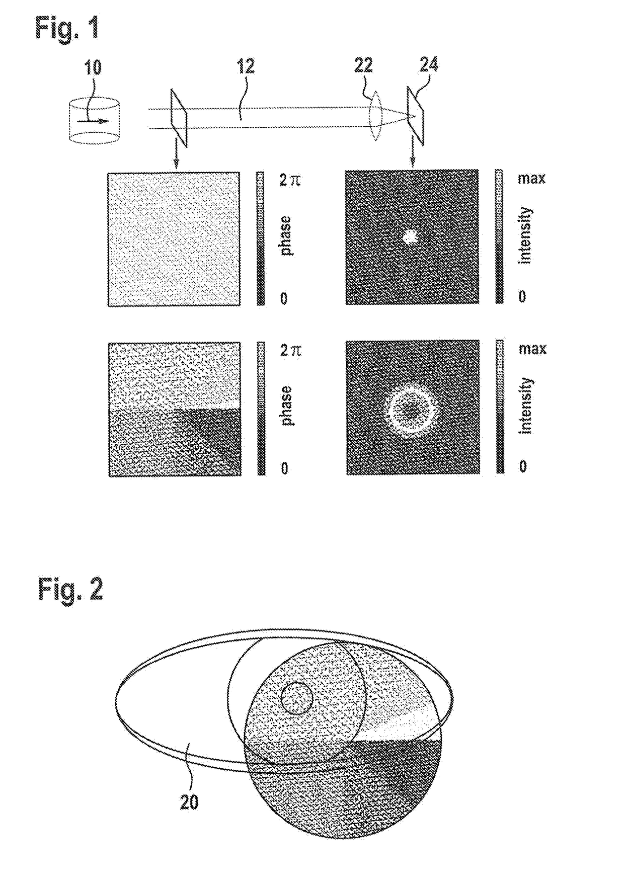
Figure 1 
Figure 2
Abstract
Description
[0001] The present application claims the benefit under 35 U.S.C. § 119 of German Patent No. DE 102017213706.1 filed on Aug. 7, 2018, which is expressly incorporated herein by reference in its entirety.FIELD
[0002] The present invention relates to a LIDAR system, preferably an eye-safe LIDAR system.BACKGROUND INFORMATION
[0003] LIDAR (Light Detection and Ranging) is becoming increasingly significant in the surroundings detection of motor vehicles or robots. Even though various technical specific embodiments exist, the presence, distance, and, if necessary, speed of other objects is generally detected by emitting light and subsequently detecting the radiation reflected by illuminated surfaces. In particular, a laser beam may be utilized for scanning the surroundings. A typical method is based on the approach that individual laser pulses are emitted in rapid succession by an appropriate LIDAR system in different spatial directions in order to scan the surroundings and the di...
Examples
Embodiment Construction
[0035]FIG. 1 shows phase fronts of collimated beams and intensity distributions after focusing, using the example of a Gaussian beam (top) and a higher-order Laguerre-Gaussian beam according to the present invention (bottom). Moreover, a LIDAR system including a laser radiation source 10 for generating coherent laser radiation 12 is schematically represented, generated laser radiation 12 being focused onto an image plane by a lens 22 in the further progression of the beam. In particular, lens 22 may be lens of an eye 20 and image plane 24 may be a corresponding retina 24.
[0036]The particular phase fronts (phase distribution) before the focusing are represented for the cutting plane indicated close to the LIDAR system and the corresponding intensity distributions in the image plane after the focusing are represented for the cutting plane indicated far from the LIDAR system. The upper row shows typical distributions for a Gaussian beam of a conventional LIDAR system. The lower row sh...