
Diffuser insert for coal fired burners
a technology of diffuser insert and coal burner, which is applied in the direction of gas current separation, combustion types, lighting and heating apparatus, etc., can solve the problems of loss on ignition, distribution problems tend to occur, and unbalanced stream, and achieve the effect of simplifying the installation tasks
Patent Information
- Authority / Receiving Office
- US · United States
- Current Assignee / Owner
- Publication Date
- 2005-01-11
- Estimated Expiration
- Not applicable · inactive patent
Smart Images
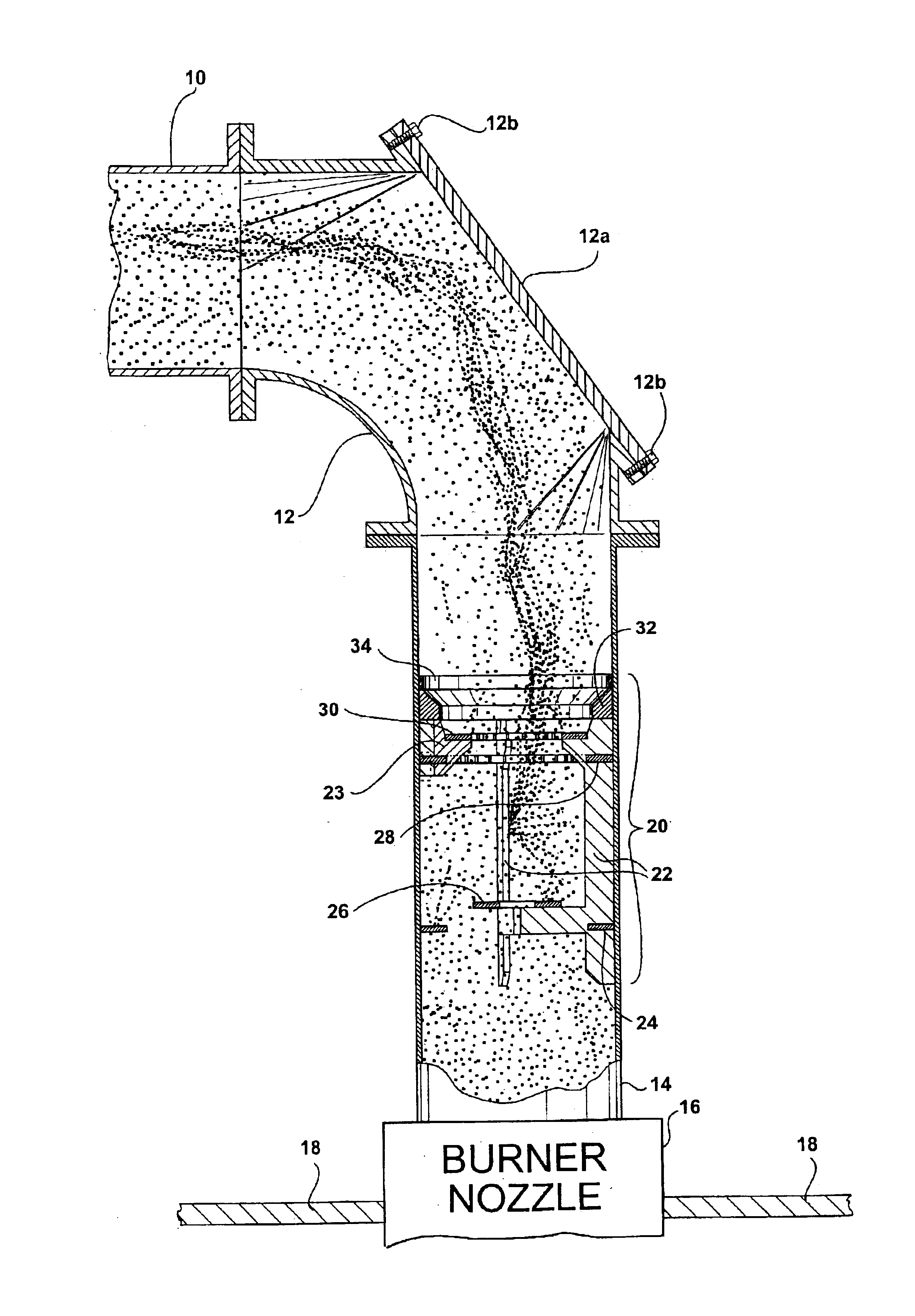
Figure 1 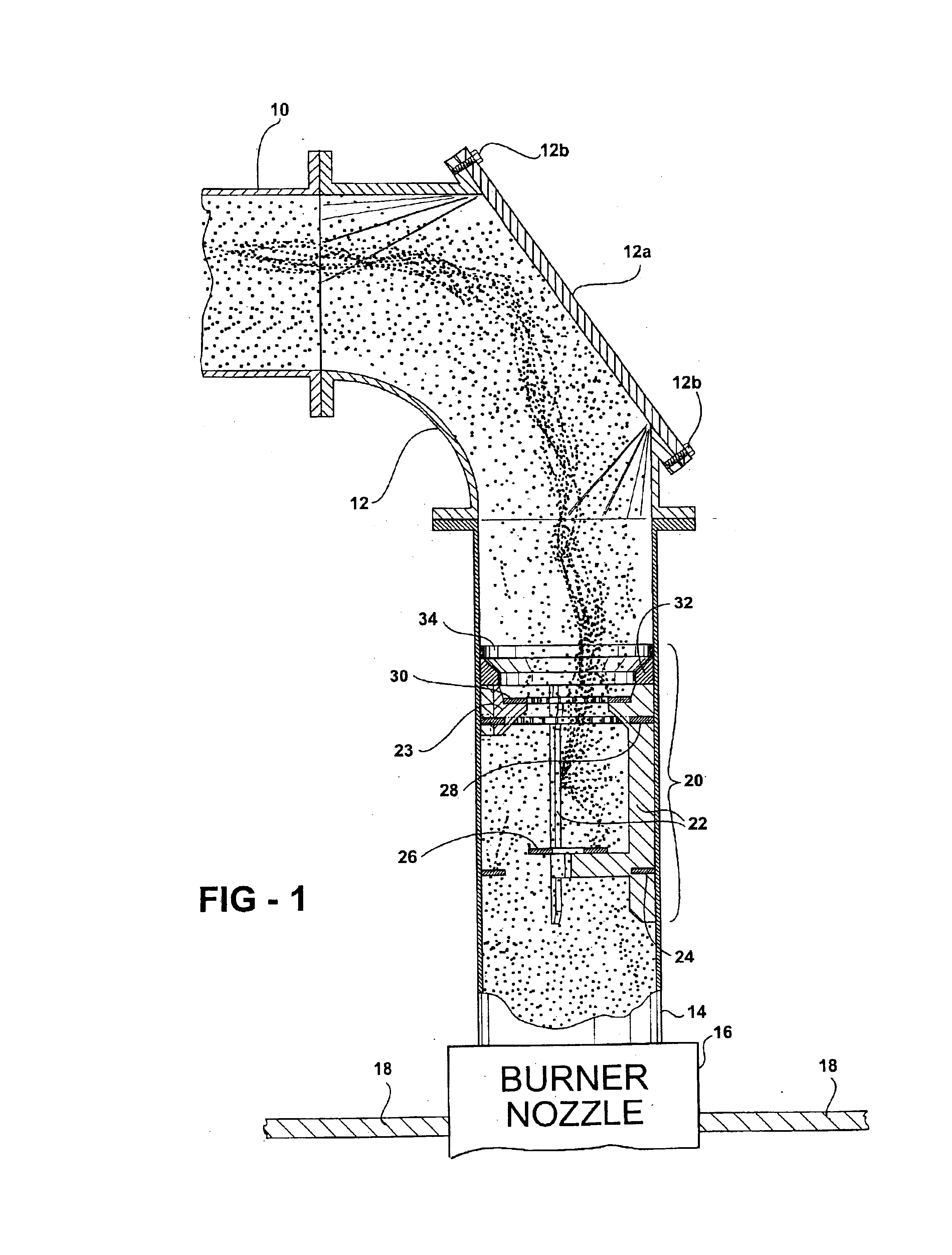
Figure 2 
Figure 3
Abstract
Description
FIELD OF THE INVENTIONThe present invention is in the field of diffuser structure used in a coal classifying and delivery flow path between a pulverizer and a combustion chamber in a coal-fired power plant.BACKGROUND OF THE INVENTIONIn the field of coal pulverizing mills there are generally two types of mills, characterized by the manner in which the pulverized coal is delivered from the mills to a combustion chamber: “suction” mills using exhauster fans to pull the pulverized coal fines from the mill through discharge pipes; and, fanless “pressurized” mills that typically entrain the pulverized coal fines in a stream of pressurized air originating at the mill.Each type of mill presents its own problems with respect to the goal of supplying an even, balanced flow of coal fines through multiple pipes to multiple burners in the combustion chamber. In suction mills, for example, the exhauster fan tends to throw coal in an unbalanced stream, with heavier particles settling out to one si...
Examples
Embodiment Construction
Referring first to FIG. 1, a pipe 10 delivers a flow of pulverized coal and air from a source of pulverized coal such as a pulverizer / classifier (not shown) to a burner nozzle 16 mounted in the wall of a combustion chamber 18. The end of pipe 10 is re-routed into alignment with burner nozzle 16 in common fashion, using an elbow pipe section 12 and a short length of connector pipe 14 between the elbow and the burner nozzle. This general arrangement of piped coal supply from a classifier to a combustion chamber is well known, and the specifics of burner nozzle, combustion chamber, piping, and classifier can vary as is known to those skilled in the art.
As noted above, the typical combustion chamber is supplied with many burner nozzles, for example from two to twelve. Attempts are usually made upstream, sometimes beginning at the classifier itself, to ensure that the flow of pulverized coal is evenly balanced among the burners. Once the coal reaches the burner nozzles, the nozzles thems...