
Radiator element
a technology of radiator element and radiator head, which is applied in the direction of gaseous heating fuel, combustion type, stove or range, etc., can solve the problems of brittle ceramic radiator, easy damage, and easy damage, and achieve the effect of reducing the risk of flashback damage, and reducing the service life of the radiator
Patent Information
- Authority / Receiving Office
- US · United States
- Patent Type
- Patents(United States)
- Current Assignee / Owner
- Publication Date
- 2005-05-24
- Estimated Expiration
- Not applicable · inactive patent
Smart Images
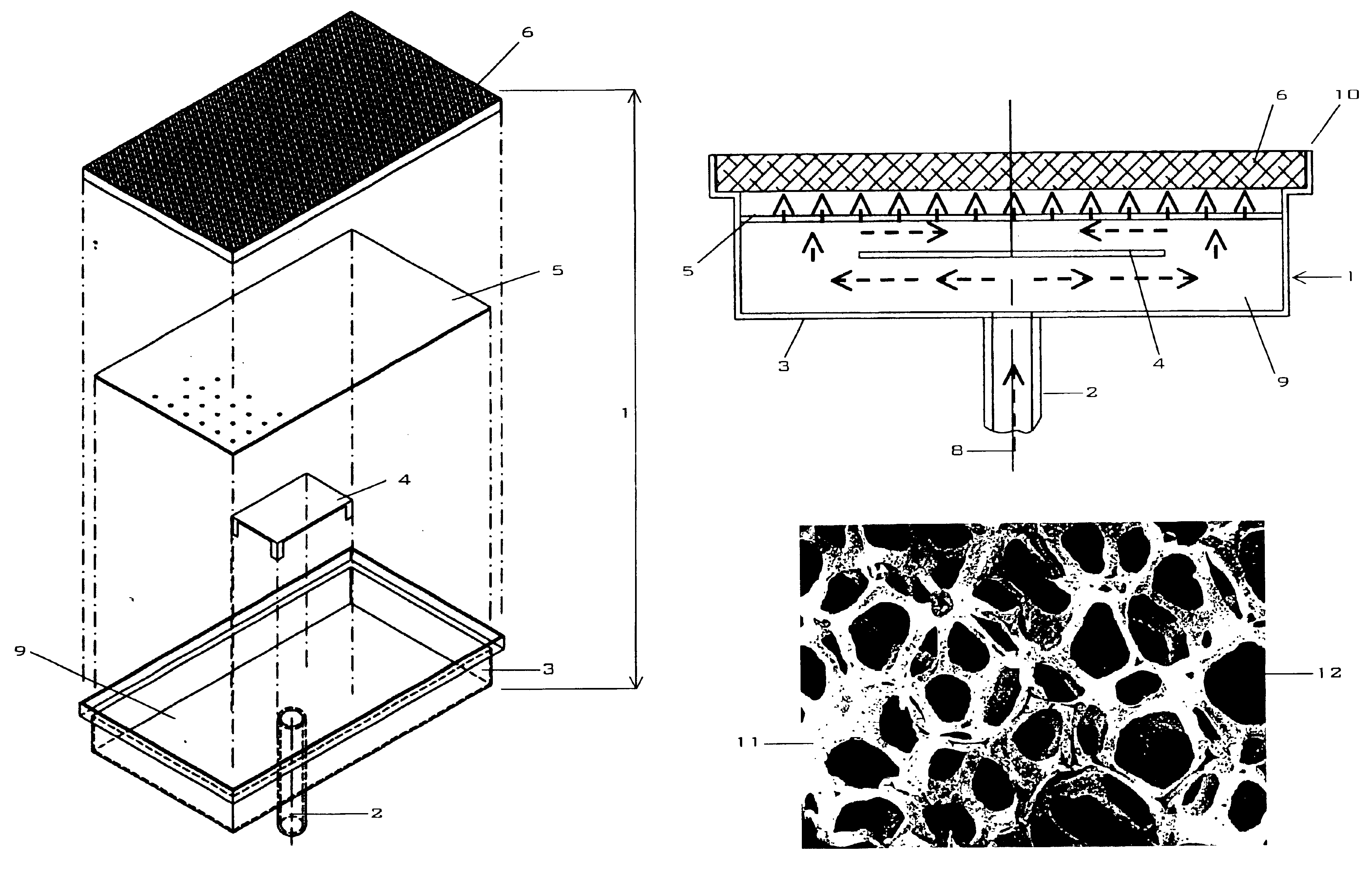
Figure 1 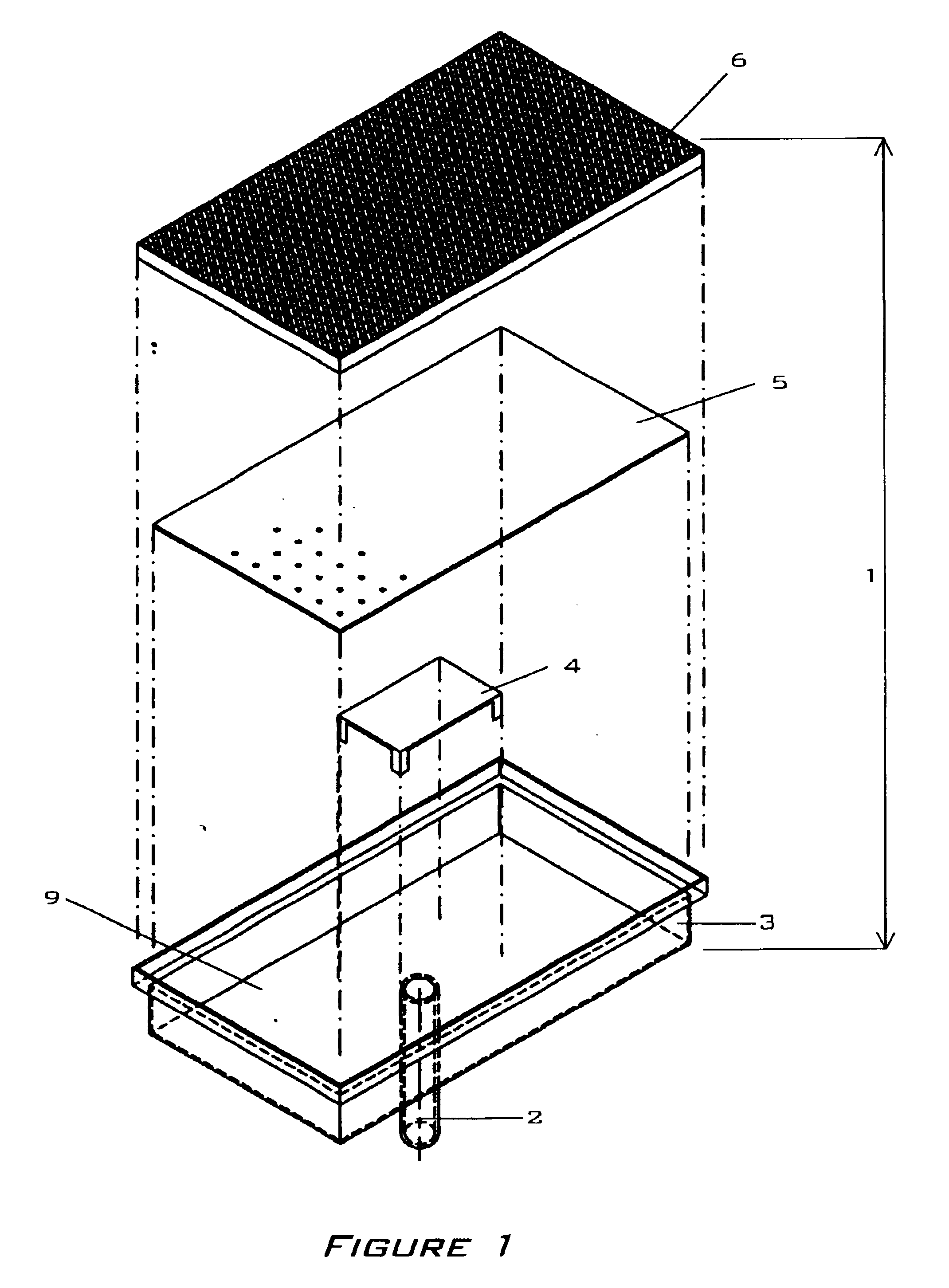
Figure 2 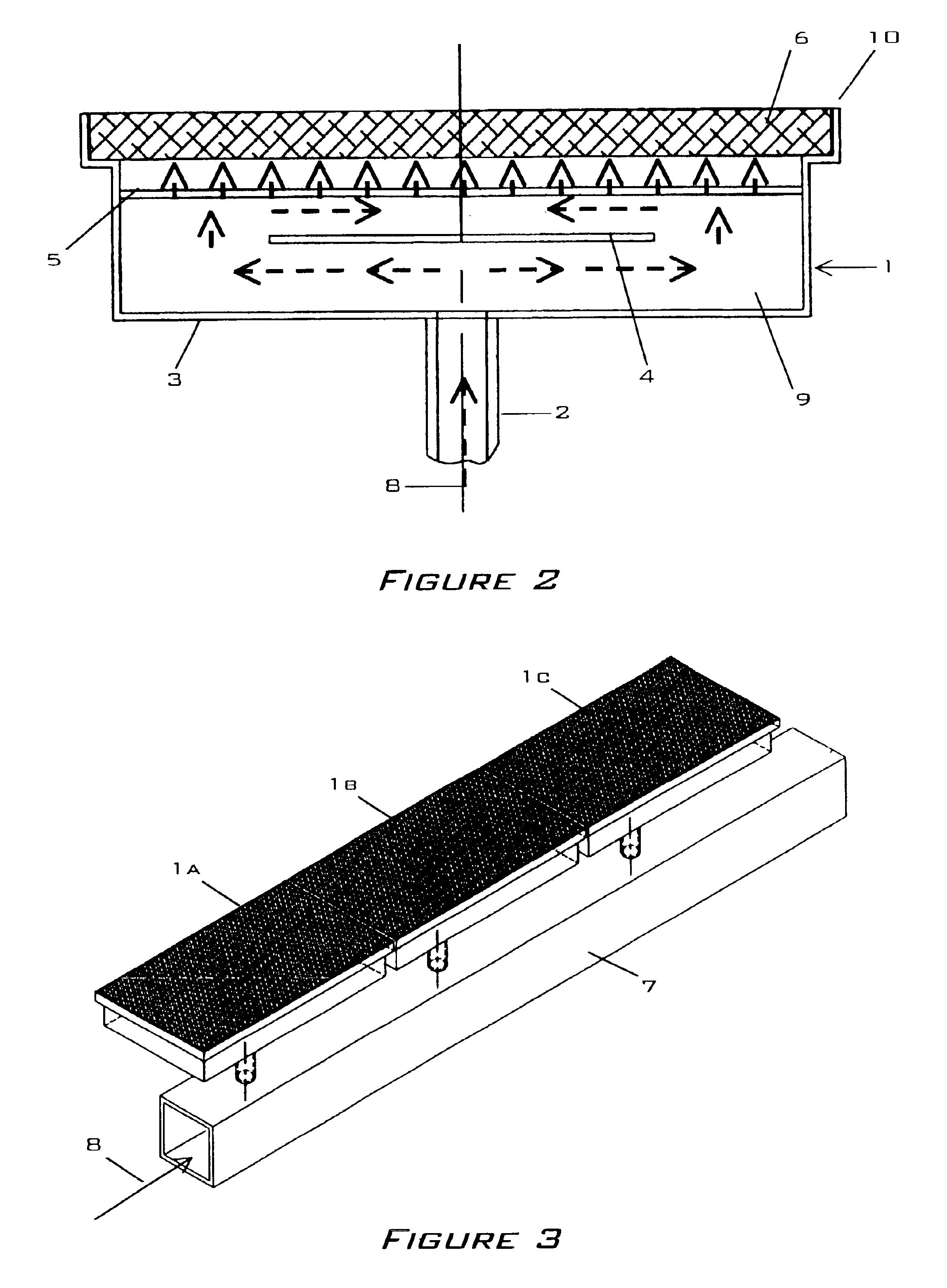
Figure 3
Abstract
Description
CROSS REFERENCE TO RELATED APPLICATIONS
[0001] This application claims benefit under 35 U.S.C. 119(e) from U.S. Provisional Application No. 60 / 323,446 filed on Sep. 19, 2001.FEDERALLY SPONSORED RESEARCH OR DEVELOPMENT
[0002] None.BACKGROUND OF THE INVENTION
[0003] 1. Field of the Invention
[0004] The present invention generally relates to a radiant burner fueled by a gaseous fuel-oxidant mixture. Specifically, the invention is a radiator element composed of a metal foam for use within a radiant burner.
[0005] 2. Description of Related Art
[0006] Radiant burners are commonly employed for a variety of purposes including heating, drying, and decontamination in such industries as paper manufacture, textile processing, and food preparation.
[0007] A typical burner is composed of an inlet attached to a plenum with a radiator element attached to the front of the burner. A baffle and diffuser are provided within the plenum in some embodiments so to optimize the flow of a fuel-oxidant mixture onto the rad...
Examples
Embodiment Construction
[0033]FIGS. 1, 2, and 3 describe the application of the present invention to a radiant burner 1. While planar applications are shown and described other shapes including but not limited to cylinders and tubes are also possible. FIG. 4 shows an exemplary metal foam embodiment of the present invention.
[0034]FIGS. 1 and 2 show a typical burner 1 comprised of an inlet 2, a plenum 3, a baffle element 4, a diffuser element 5, and a radiator element 6. FIG. 3 shows the arrangement of several burners 1a, 1b, 1c along a single manifold 7 in an arrangement typically found in a textile dryer. An igniter device as understood in the art is mounted adjacent to the radiator element 6 as so to initiate combustion of a fuel-oxidant mixture 8.
[0035]The plenum 3 is comprised of a five-sided structure having an open front 10 over which a radiator element 6 is fixed. A typical plenum 3 is composed of a metal either cast, molded or formed via methods understood in the art. An inlet 2 is attached to one s...