
Vehicular lamp
a technology of a vehicle and a lamp body is applied in the field of vehicles, which can solve the problems of increasing the size of the control circuit portion, limiting the application of conventional structures, and limiting the space left for certain amount of space, so as to achieve a more compact overall lamp, high heat loss, and high heat loss
Patent Information
- Authority / Receiving Office
- US · United States
- Patent Type
- Patents(United States)
- Current Assignee / Owner
- Publication Date
- 2010-04-20
- Estimated Expiration
- Not applicable · inactive patent
Smart Images
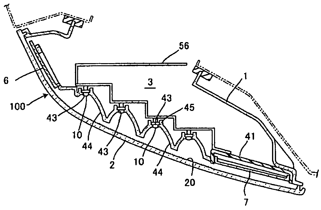
Figure 1 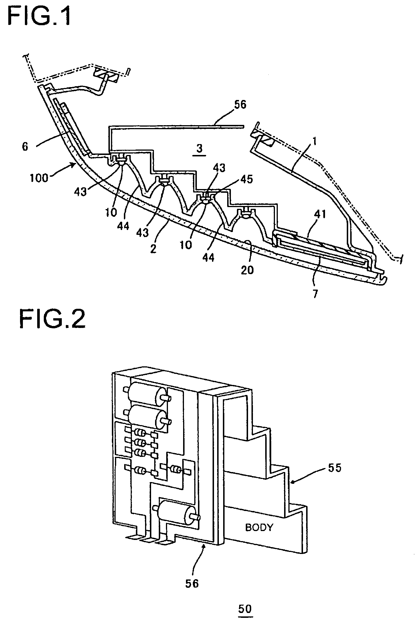
Figure 2 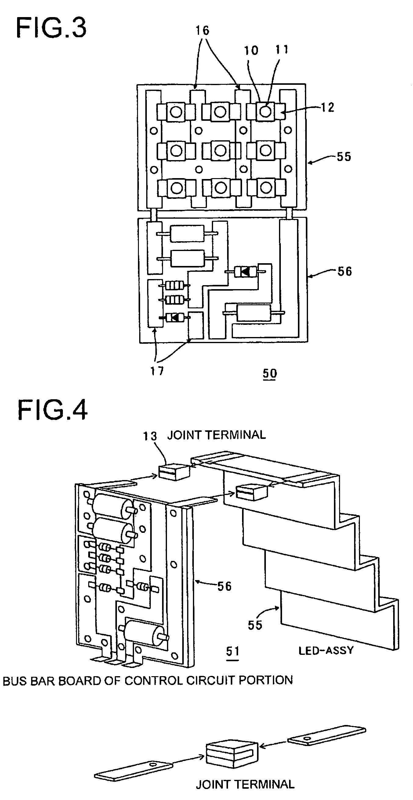
Figure 3
Abstract
Description
BACKGROUND OF INVENTION
[0001] 1. Field of the Invention
[0002] The present invention relates to a vehicular lamp using an LED as a light source.
[0003] 2. Background Art
[0004] In recent years, a variety of LEDs with excellent light emission efficiency and power consumption characteristics are being used as a light source in a vehicular lamp (see Patent Document 1 for an example). Such a vehicular lamp is provided with an LED light source assembly portion mounted with an LED and a unit that combines the LED light source assembly portion with a control circuit portion. As shown in FIG. 12, a conventional control circuit portion uses a printed circuit board 8, which is connected to the back side of the LED light source assembly portion by a jump cord 15.
[0005] [Patent Document 1] U.S. Pat. No. 6,715,909SUMMARY OF INVENTION
[0006] In order to make a smaller overall unit, it is preferable that the control circuit portion and an LED light source assembly portion 9 are arranged adjacent to one anot...
Examples
Embodiment Construction
[0030]FIG. 1 is a horizontal cross-sectional view showing a structure of a vehicular lamp according to one or more embodiments of the present invention. Here, a tail and stop lamp, i.e., a marker lamp, will be used in the following description as an example of a vehicular lamp according to one or more embodiments of the present invention.
[0031]A tail and stop lamp 100 is mainly structured from a lamp body 1, a curved front cover 2, a lamp chamber 3 that is defined by the lamp body 1 and the front cover 2, a curved reflector 4 that is disposed inside the lamp chamber 3, and a bus bar unit 5 that is provided on the back side of the reflector 4. The bus bar unit 5 is a unit provided with an LED light source assembly portion 55 that is mounted with an LED 10, which acts as a light source of the tail and stop lamp 100, and a control circuit portion 56 that controls the light emission of the LED. In the example shown in the drawing, the bus bar unit 5 is fixed to the reflector 4 on a vehi...