
Apparatus and methods of transferring heat with a differential magneto-thermal force
a technology of differential magneto-thermal force and apparatus, applied in the field of apparatus and methods of transferring heat with a differential magnetothermal force, can solve the problems of energy waste and unaddressed need in the art, and achieve the effect of improving the efficiency of the engin
Patent Information
- Authority / Receiving Office
- US · United States
- Patent Type
- Patents(United States)
- Current Assignee / Owner
- Publication Date
- 2011-12-27
Smart Images
Figure 1 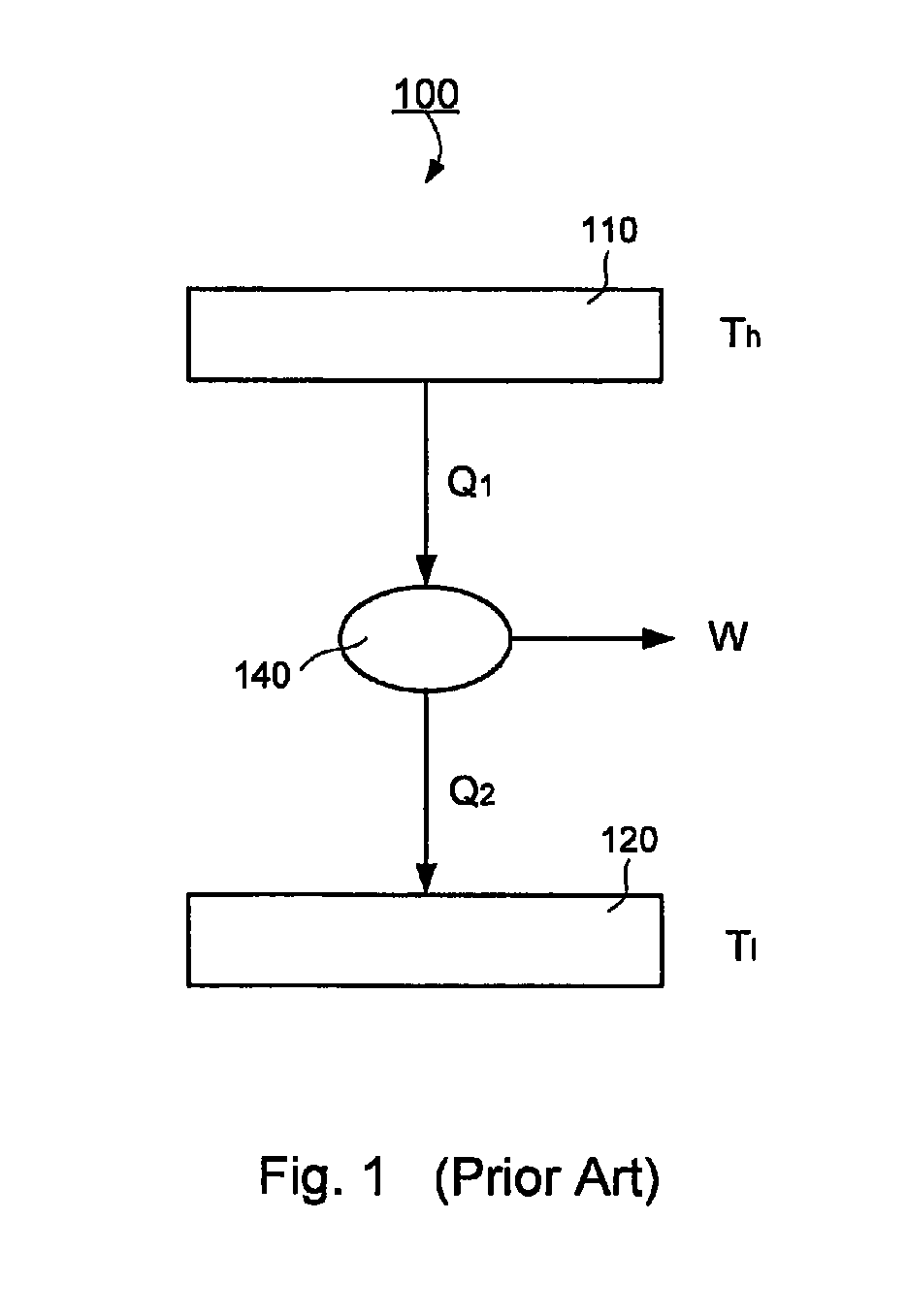
Figure 2 
Figure 3
Abstract
Description
CROSS-REFERENCE TO RELATED PATENT APPLICATION
[0001] This application claims the benefit, pursuant to 35 U.S.C. §119(e), of U.S. provisional patent application Ser. No. 60 / 692,460, filed Jun. 21, 2005, entitled “Differential Magneto-Thermal Single-Heat-Source Engine,” by Weili Luo, which is incorporated herein by reference in its entirety.
[0002] Some references, which may include patents, patent applications and various publications, are cited in a reference list and discussed in the description of this invention. The citation and / or discussion of such references is provided merely to clarify the description of the present invention and is not an admission that any such reference is “prior art” to the invention described herein. All references cited and discussed in this specification are incorporated herein by reference in their entireties and to the same extent as if each reference was individually incorporated by reference. In terms of notation, hereinafter, “[n]” represents the nth...
Examples
examples and implementations
[0073]Without intent to limit the scope of the invention, further exemplary methods and their related results according to the embodiments of the present invention are given below. Note again that titles or subtitles may be used in the examples for convenience of a reader, which in no way should limit the scope of the invention. Moreover, certain theories are proposed and disclosed herein; however, in no way they, whether they are right or wrong, should limit the scope of the invention.
[0074]FIG. 1 illustrates typical working principle in the existing technology of a general engine based on Carnot cycle. The high temperature heat source at temperature Th provide heat Q1 to do work, W, to outside. In this technology, amount of heat Q2 cannot be converted to work and has to be deposited to the low temperature source Tl. In most cases, the heat was released to the environment as in steam engines, car engines, combustion engines, and all other modern engines, as well as all power genera...