
Seal assembly
a technology of diaphragm and seal assembly, which is applied in the direction of engine seals, valve arrangements, diaphragm valves, etc., can solve the problems of elastomeric body may be exposed to relatively harsh fluid composition, fluid temperature and/or fluid pressure, and may be subject to variable tightening forces and extrusion forces, etc., and may be subject to significant labor and parts costs, and may be subject to system
Patent Information
- Authority / Receiving Office
- US · United States
- Patent Type
- Patents(United States)
- Current Assignee / Owner
- Publication Date
- 2015-08-18
- Estimated Expiration
- Not applicable · inactive patent
Smart Images
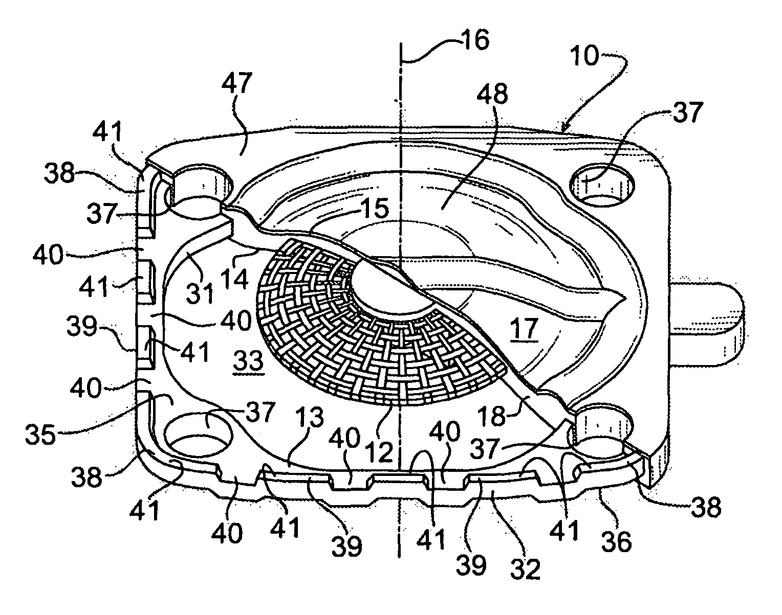
Figure 1 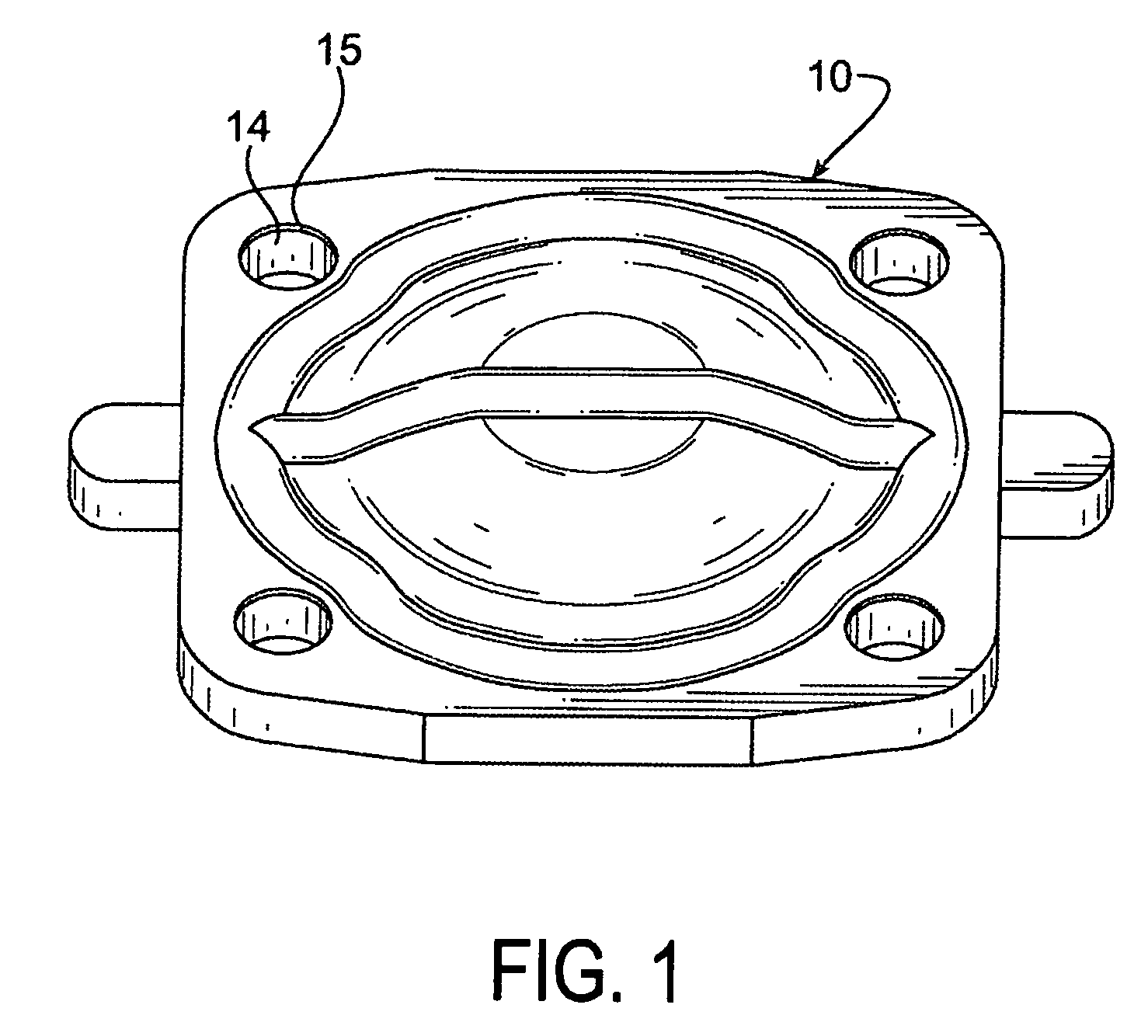
Figure 2 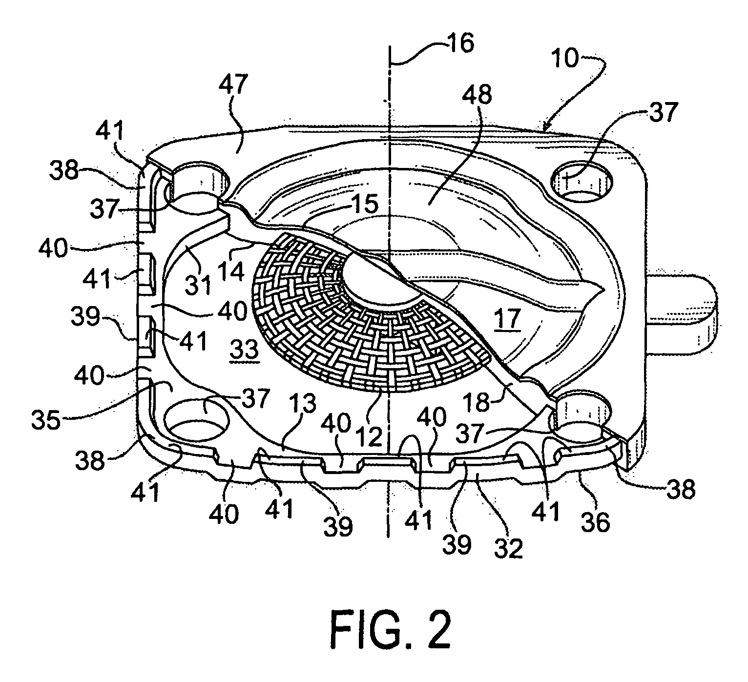
Figure 3
Abstract
Description
CROSS REFERENCE TO RELATED APPLICATIONS
[0001] The present application claims the benefit of the filing date of U.S. Provisional Patent Application Ser. No. 61 / 252,850 filed Oct. 19, 2009, the disclosure of which is incorporated herein by reference in its entirety.TECHNICAL FIELD
[0002] This invention relates generally to seal assemblies. More particularly, this invention relates to a diaphragm seal assembly for use in a fluid control valve.BACKGROUND OF THE INVENTION
[0003] Diaphragm seal assemblies are widely used in fluid control valves to control the flow of a wide variety of fluids through the valve at various conditions of temperature, pressure and other conditions. Such diaphragm seal assemblies typically include an elastomeric body. A stationary peripheral portion of the elastomeric body may be secured to a housing of the fluid control valve, and a diaphragm portion of the elastomeric body may be carried by the stationary peripheral portion for movement between a closed or sealed ...
Examples
Embodiment Construction
[0027]The principles, embodiments and operation of the present invention are shown in the accompanying drawings and described in detail herein. These drawings and this description are not to be construed as being limited to the particular illustrative forms of the invention disclosed. It will thus become apparent to those skilled in the art that various modifications of the embodiments herein can be made without departing from the spirit or scope of the invention.
[0028]Referring now to FIGS. 1 and 2, a diaphragm seal assembly 10 according to one preferred embodiment of this invention is illustrated. The diaphragm seal assembly 10 includes an attachment stud 11, a reinforcing mesh 12, a rigid carrier 13, an elastomeric body 14, and an elastomeric film 15. The attachment stud 11, reinforcing mesh 12, rigid carrier 13, elastomeric body 14 and elastomeric film 15 are each coaxially arranged about a longitudinal axis 16. As also further described below, the diaphragm seal assembly 10 inc...