Air clamper in use for principal axis of lathe

A technology of pneumatic clamping and lathe spindle, applied in positioning devices, clamping, turning equipment, etc., to achieve the effect of good versatility, long service life and good sealing performance

Inactive Publication Date: 2008-10-01
宾焕南
View PDF7 Cites 3 Cited by
  • Summary
  • Abstract
  • Description
  • Claims
  • Application Information

AI Technical Summary

Problems solved by technology

If you want to further increase the spindle speed, the manufacturer who specializes in producing this cylinder thinks that there is a certain degree of difficulty

Method used


Image

  • Air clamper in use for principal axis of lathe
  • Air clamper in use for principal axis of lathe
  • Air clamper in use for principal axis of lathe

Examples


Embodiment Construction

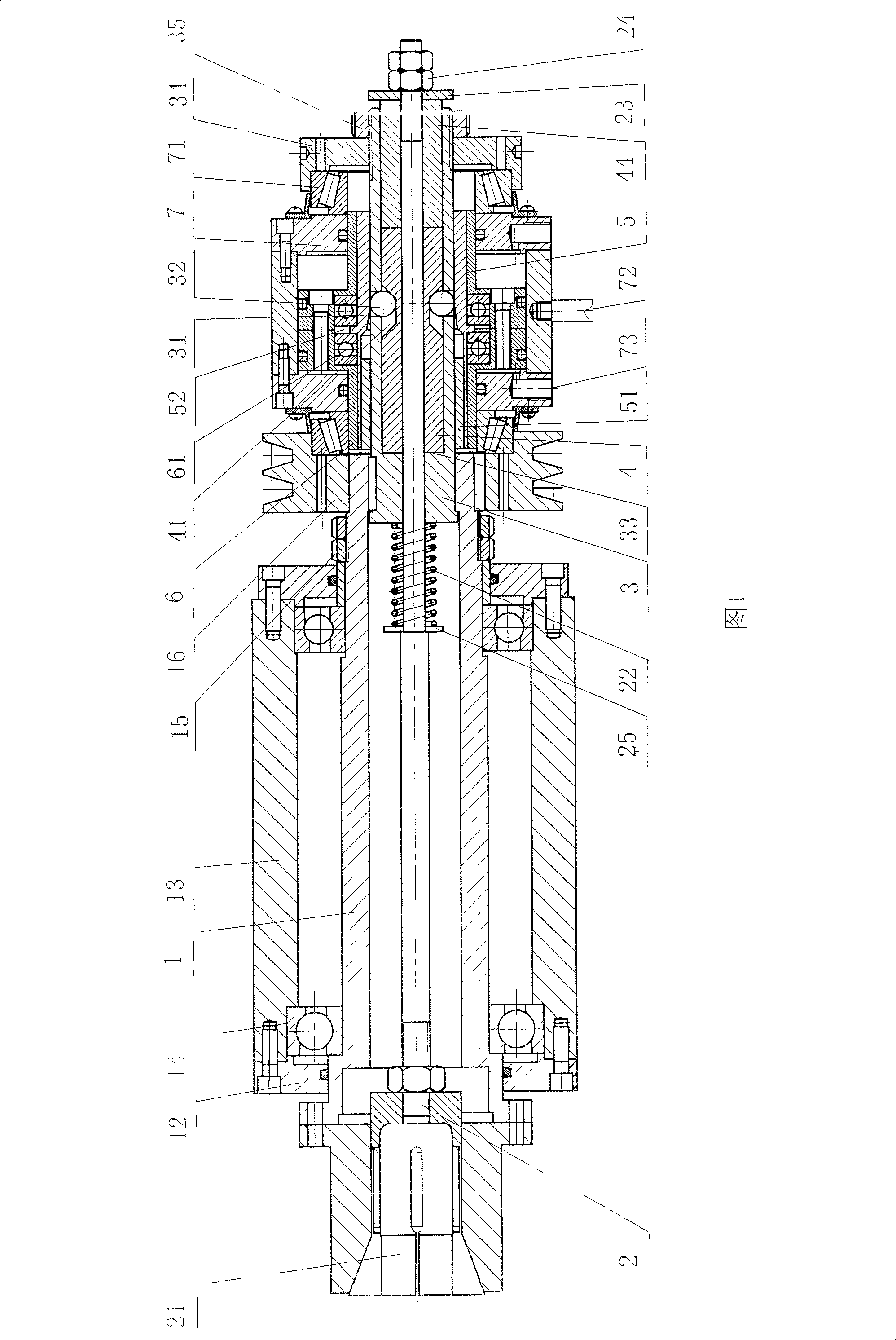
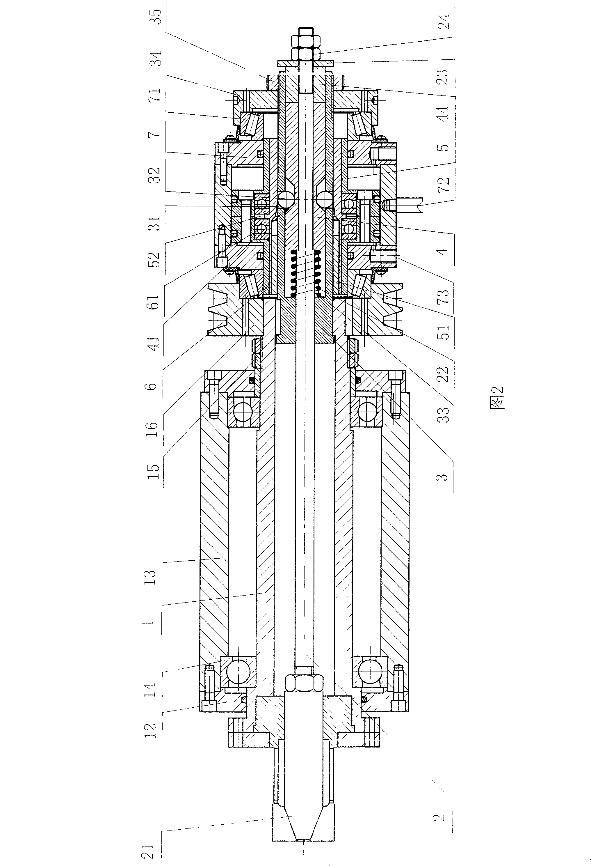
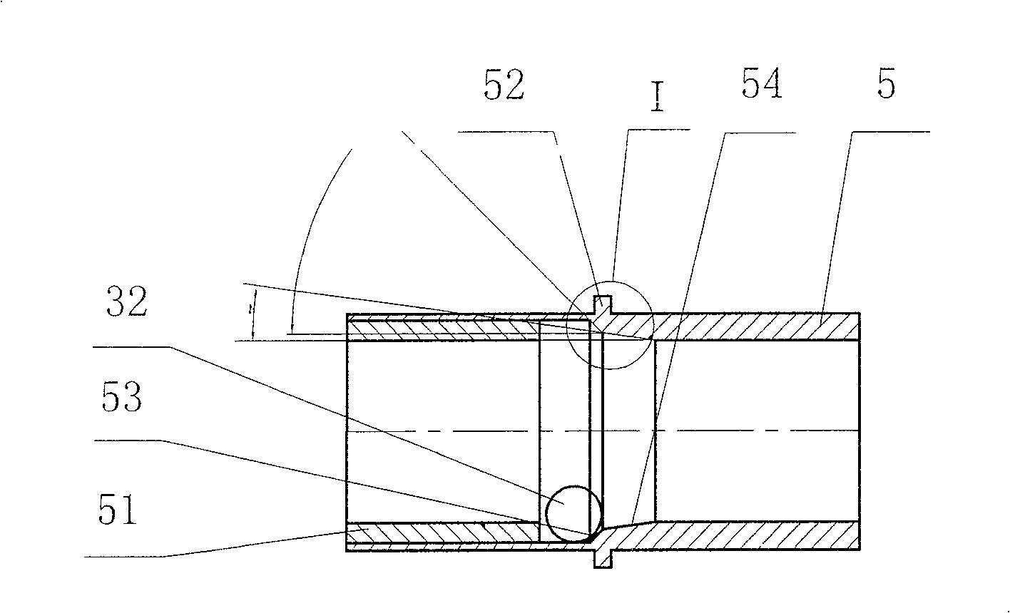
[0025] A pneumatic clamping device for the spindle of a lathe shown in the accompanying drawing, the spindle 1 passes through the front and rear end covers 12 on it and the axle seat bearing 14 arranged on the inner wall of the front and rear ends of the spindle seat 13 and passes through the tail of the spindle 1 The locking nut 15 on the top is fixedly connected with the main shaft seat 13 as a whole. The center of the main shaft 1 is provided with a pull rod 2, the front end of the pull rod 2 is provided with a clip spring 21, and the rear portion of the pull rod 2 is provided with a loosening mechanism, which includes a steel ball sleeve 3 arranged on the inner wall pull rod 2 at the tail of the main shaft 1. The steel ball 32 in the radial through hole 31 of the steel ball sleeve 3, the pull rod sleeve 4 adapted to the steel ball sleeve 3, the steel ball ring groove 41 located in the middle of the pull rod sleeve 4, and the long and short ends 42, 43 of the pull rod sleeve...


PUM


Abstract

A pneumatic fixture for the mainshaft of machine-tool is composed of a mainshaft with bearings, a central pull rod in said mainshaft and with front end connected to clamping spring and back end with clamp releasing mechanism, a steel ball sleeve on said pull rod and with radial through holes, pull rod sleeve in said steel ball sleeve and with a ring slot, steel balls in said ring slot and matched with external sleeve via said radial through holes, a piston module with bevel bearing, and a cylinder module.

Description

technical field [0001] The invention relates to an auxiliary device of a lathe, in particular to a pneumatic clamping device with a wedge mechanism added to the tail of the main shaft of the lathe. Background technique [0002] The existing pneumatic lathe clamping device is economical, convenient and reliable, and has been widely used in the machinery industry, especially in special-purpose or semi-automatic lathes. There are two types of installation: [0003] 1. The air cylinder is installed on the main shaft, and the air cylinder rotates together with the main shaft, and a distributor controlled by a reversing valve is arranged at the back, and the distributor does not rotate with the main shaft. In this installation method, the force of the cylinder is on the main shaft itself and not on the main shaft seat superior; [0004] 2. The cylinder is installed on the machine tool, and the piston rod of the cylinder and the pull rod of the clip spring are connected through a...

Claims


Application Information

Patent Timeline
Patent Type & Authority Patents(China)
IPC IPC(8): B23B31/00B23Q3/12
Inventor 宾焕南宾莲洁
Owner 宾焕南
Why Eureka
Try Eureka