Mop

A mop and mop rod technology, applied in the field of mops, can solve the problems of inconvenient removal, lateral splashing of sewage, and inability to use back and forth push-pull, etc., to improve the ability to remove stubborn dirt, facilitate the removal of dirt, and have good water absorption performance. Effect

Inactive Publication Date: 2009-08-12
赵一美
View PDF7 Cites 2 Cited by
  • Summary
  • Abstract
  • Description
  • Claims
  • Application Information

AI Technical Summary

Problems solved by technology

And the herringbone metal frame is easy to touch the furniture or the wall, causing damage to the furniture or the wall
[0004] 2. Since the above-mentioned mopping roller can rotate in one direction, it can only push the roller in one direction when wiping the floor, and cannot use the way of pushing and pulling back and forth to mop the floor, so that the floor mopping device cannot adapt to users who have the habit of pushing and pulling back and forth
In particular, when there is more stubborn dirt on the ground, the mopping method of pushing and pulling back and forth can easily remove the dirt, while the mopping method of pushing in one direction is not easy to remove the dirt; stubborn dirt
[0005] 3. The mopping roller of the above-mentioned technical scheme adopts short-haired chemical fiber textiles, and 4 rubber bands are used to strangle the short-haired chemical fiber textiles; when cleaning, the 4 elastic bands need to be untied, and the short-haired chemical fiber textiles are cleaned, so that the floor wiper very inconvenient to use
Furthermore, the mopping roller wrapped in short-haired chemical fiber textiles is not easy to remove the dirt from the chemical fiber textiles during cleaning. When holding the handle to squeeze the water, the sewage will splash sideways
Brings a lot of inconvenience to use

Method used


Image

  • Mop
  • Mop
  • Mop

Examples


Embodiment Construction

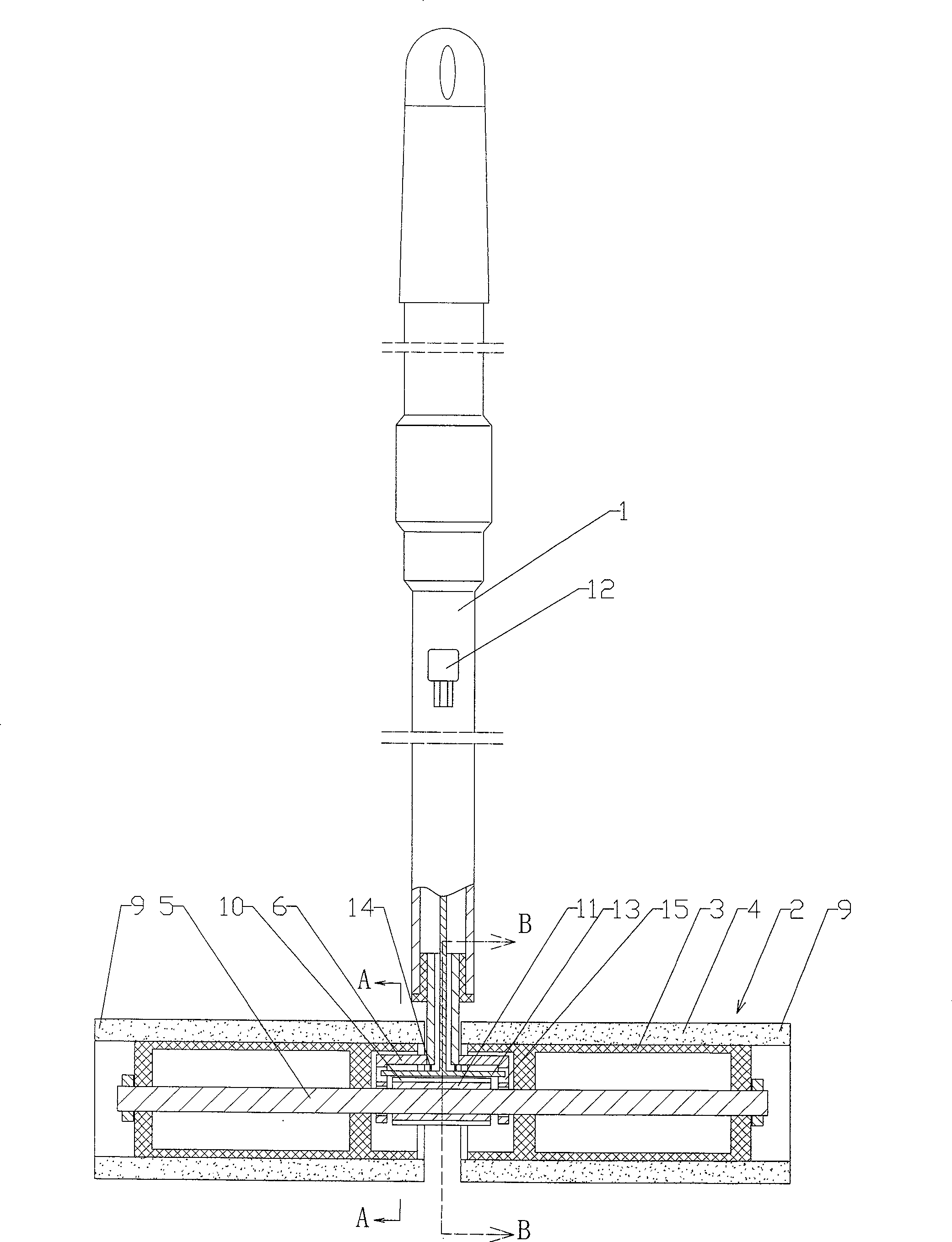
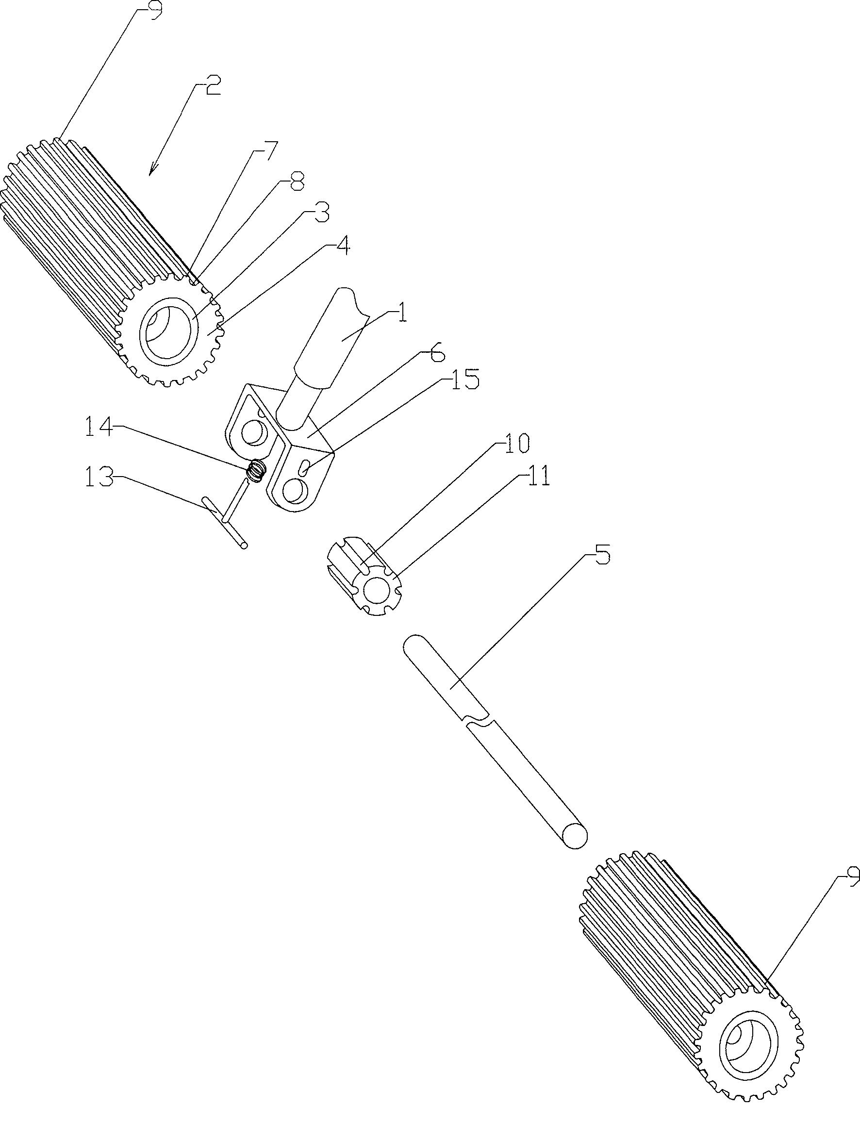
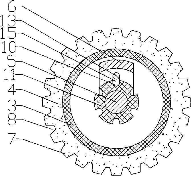
[0051] to combine Figure 1-Figure 6 As shown: a wiping roller 2 is provided under the mop rod 1 of this embodiment, and the wiping roller includes: a roller frame 3 and a wiper 4 arranged on the roller frame. Wiping rollers 2 are arranged on both sides of the mop rod 1, and a connecting shaft 5 is arranged between the wiping rollers on both sides; the mop rod is provided with a connecting piece 6, and the mop rod 1 is connected to the connecting shaft 5 through the connecting piece 6; the locking mechanism controls the wiping roller 2 Turn and stop.

[0052] In this embodiment, the wiper 4 is collodion wrapped outside the roller frame, and ribs 7 and grooves 8 are distributed on the outer surface of the collodion. The roller frame 3 is covered with collodion, which is ring-shaped with the collodion at the socket joint of the roller frame, and the collodion is bonded to the roller frame. The collodion on the wiping roller away from the mop bar side 9 grows out of the roller ...


PUM


Abstract

A mop is provided with a wiping roller under the mop rod, and the wiping roller comprises: a roller frame and a wiping object arranged on the roller frame. Both sides of the mop rod are provided with wiping rollers, and connecting shafts are arranged between the wiping rollers on both sides; the mop rod is provided with connecting pieces, and the mop rod is connected with the connecting shafts through the connecting pieces; the locking mechanism controls the rotation and stop of the wiping rollers. Since the wiping rollers are arranged on both sides of the mop rod, the mop rod and the connecting shaft are not easy to touch the furniture and the wall, which can effectively protect the furniture and the wall during the wiping process. At the same time, it is also beneficial to remove dirt from the corners of the ground. When the surface of the wiping roller in contact with the ground is soiled, the locking mechanism is operated to turn the surface of the wiping roller not in contact with the ground to a position in contact with the ground, and then the ground can be continued to be wiped.

Description

Technical field: [0001] The invention relates to a mop. Background technique: [0002] Existing mops generally consist of a mop bar and a cleaning head located at the lower end of the mop bar. All the wipes on the cleaning head will be soiled at the same time during use, so that the cleaning area of ​​the cleaning head after each cleaning is small. In order to solve this problem, Chinese patent No. 200320100211.X just proposes a kind of " roller type floor wiper ". The roller type floor mopping device of this technical scheme is composed of a handle, a herringbone metal frame, and a floor mopping roller. Turn the controller. When the roller is not rotating, pushing the roller to move can wipe the floor. When the drum is stressed in the other direction, the drum rotates to squeeze water. Only the surface of the roller that is in contact with the ground gets soiled. When the surface of the roller in contact with the ground is soiled, move the roller in the opposite direc...

Claims


Application Information

Patent Timeline
Patent Type & Authority Patents(China)
IPC IPC(8): A47L13/24A47L13/20
Inventor 赵一美
Owner 赵一美
Why Eureka
Try Eureka