Passage barrier

A technology of access control and blocking parts, which is applied in the field of access control devices, can solve problems such as damaging the external form of access control devices, and achieve the effect of saving structural space

Inactive Publication Date: 2007-08-29
SCHEIDT BACHMANN GMBH
View PDF4 Cites 8 Cited by
  • Summary
  • Abstract
  • Description
  • Claims
  • Application Information

AI Technical Summary

Problems solved by technology

The disadvantage of this construction is, on the one hand, that the displacement of the blocking members 94 and 96 impairs the symmetrical external form of the access control device 80.
A major disadvantage of the access control device 110 shown is that, due to the identical construction of the un

Method used


Image

  • Passage barrier
  • Passage barrier
  • Passage barrier

Examples


Embodiment Construction

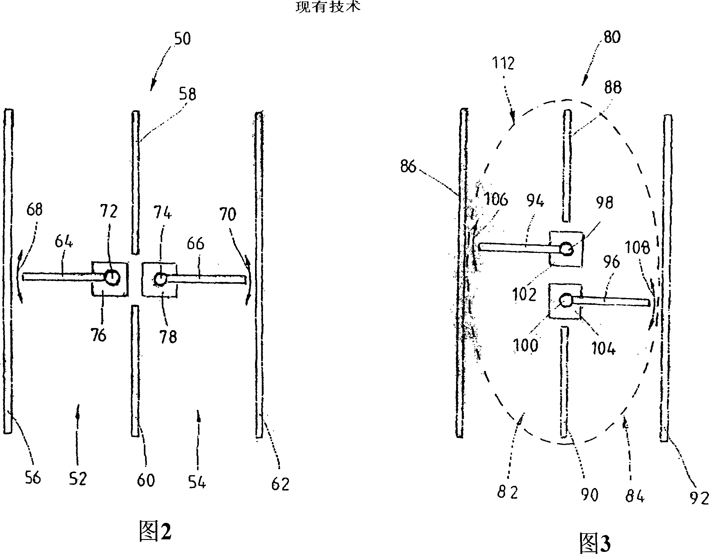
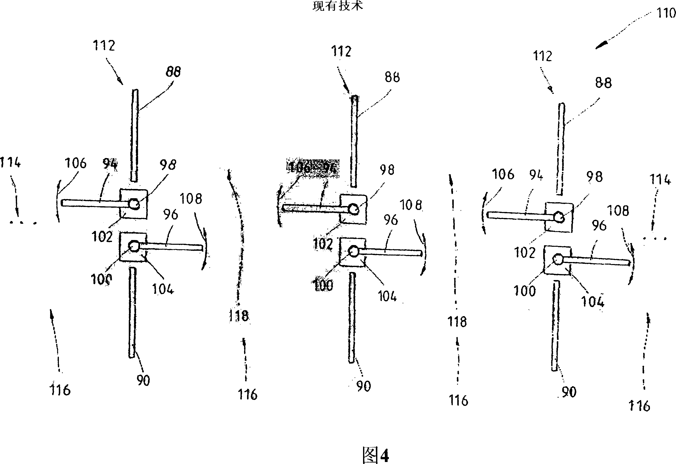
[0019] Figures 2, 3 and 4 have already been introduced in the background art section, so the details of these figures will not be repeated below.

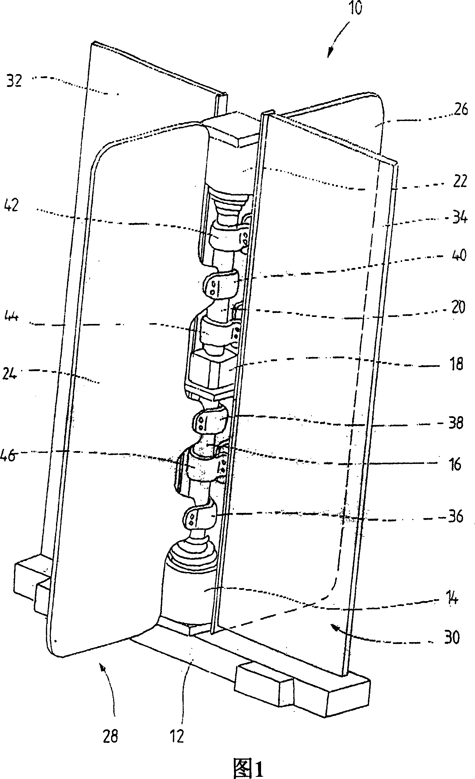
[0020] FIG. 1 shows a perspective view of an embodiment of an access control device 10 according to the invention. The access control device 10 comprises a base 12, from which a vertically upward extension of a column is arranged, and viewed from the bottom up, the arrangement has a first motor 14, a first shaft 16 that can be driven by the first motor, a bearing structure 18, a second shaft 20 and a second motor 22 for driving the second shaft 20 . The first shaft 16 and the second shaft 20 are supported at their free ends facing each other on the bearing structure 18 in such a way that they can be driven independently of each other by the corresponding electric motors 14 and 22 .

[0021] The access control device 10 also includes two wing-shaped blocking elements 24 and 26 for selectively blocking or opening two separate passag...


PUM


Abstract

Passage barrier (10) having two barrier elements (24, 26) and two shafts (16, 20) which are aligned with one another, are separate from one another and are able to be driven by separate motors (14, 22), wherein one barrier element (24, 26) is held fixedly on each shaft (16, 20) and can be pivoted independently of the other barrier element (26, 24) by driving the corresponding shaft (16, 20).

Description

technical field [0001] The invention relates to an access control device with an automatically rotatable barrier. Background technique [0002] Access control devices of the aforesaid type are known in various embodiments and are used to selectively allow or prevent the passage of pedestrians or vehicles. In a simple construction, they can be constructed as revolving doors with two oppositely arranged and mutually centered barriers, each of which is fastened to a common gate extending vertically between the barriers and driven by means of an electric motor. on axis. Through the transmission of the shaft, the two blocking elements can then jointly pivot around the axis. If two barriers are responsible for different channels, the barriers can be pivoted independently of each other as required, for example one channel is opened while the other channel remains closed. In order to be able to pivot the two blocking elements individually, there are two shafts which can each be d...

Claims


Application Information

Patent Timeline
IPC IPC(8): E06B5/00E05F15/20
CPCE06B11/085E05Y2400/30E05Y2201/706E05Y2201/628E06B3/90
Inventor 马蒂亚斯·奥古斯蒂尼亚克迪特尔·施瓦尔德
Owner SCHEIDT BACHMANN GMBH
Why Eureka
Try Eureka