Electrical switchgear

A technology of switchgear and electric switch, applied in the direction of electric switch, high voltage/high current switch, circuit, etc., which can solve the problems of expensive design and large size

Inactive Publication Date: 2007-10-10
SIEMENS AG
View PDF5 Cites 1 Cited by
  • Summary
  • Abstract
  • Description
  • Claims
  • Application Information

AI Technical Summary

Problems solved by technology

In order to form a labyrinth, large numbers of such shields are require

Method used


Image

  • Electrical switchgear
  • Electrical switchgear
  • Electrical switchgear

Examples


Embodiment Construction

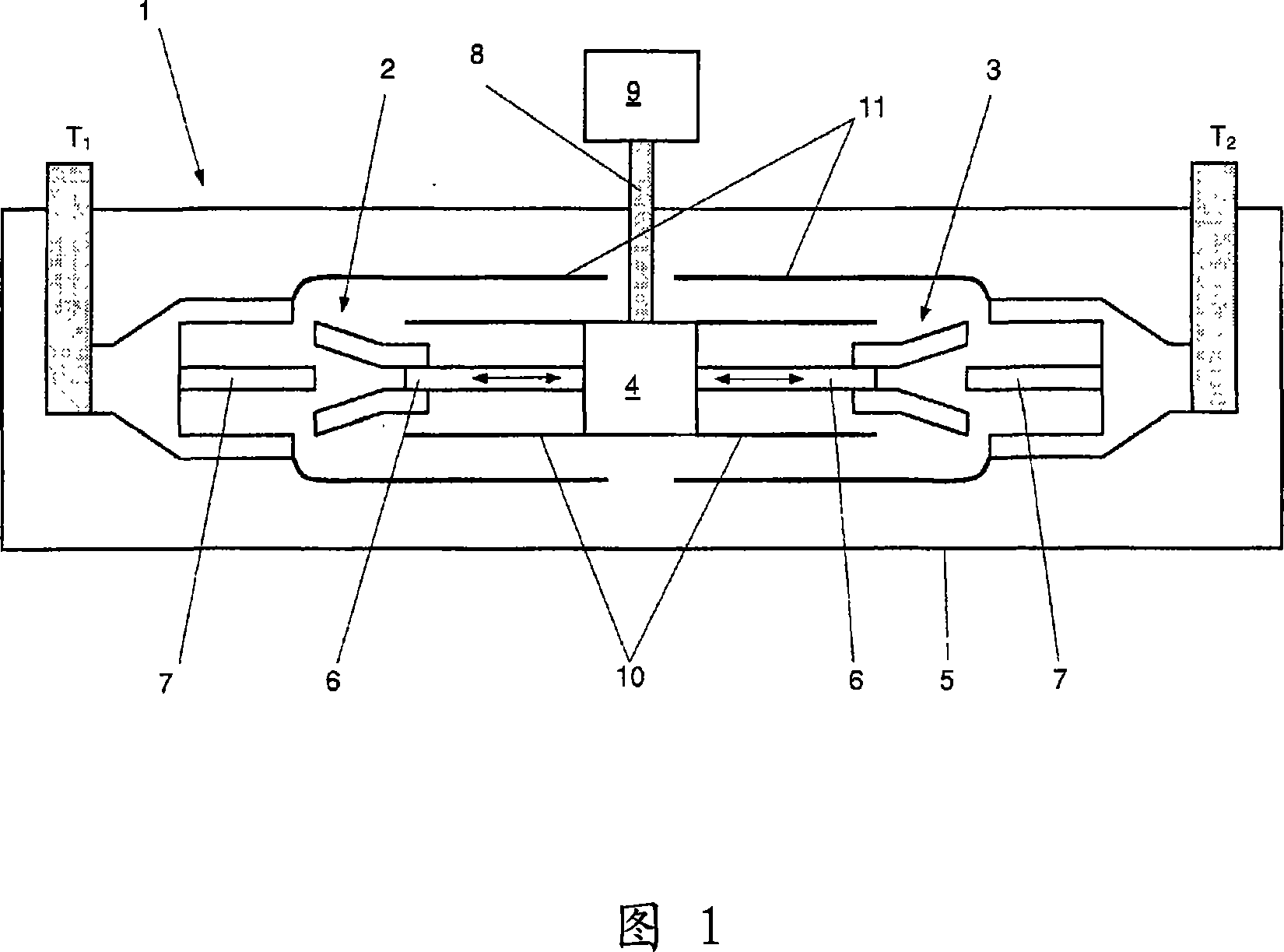
[0013] Figure 1 shows an electrical switching device 1 of the invention, eg a circuit breaker, comprising a housing 5 in which two switches 2, 3 are arranged. Two switches 2, 3 are connected in series at terminals T1 (e.g. high potential) and T 2 (for example, ground). In order to perform a switching operation (opening or closing), the moving contacts 6 (indicated by double arrows in Fig. 1) in both switches 2, 3 are moved simultaneously by the drive unit, which also serves as a means for mechanically and electrically connecting the two Connection device 4 for switches 2, 3. The drive unit 4 is arranged between the switches 2, 3 and may comprise a plurality of levers and drive rods 8 for mechanically connecting the drive unit 4 to a drive mechanism 9 (in this example located outside the housing 5), as shown in Fig. 1. The drive unit 4 can be driven by a suitable drive mechanism 9, such as known spring mechanisms, hydraulic mechanisms or electric motors, for example. The dr...


PUM


Abstract

Electrical switchgear, e.g. a circuit breaker, must in general provide good dielectric strength in open position in order to avoid discharge. To improve the dielectric strength capacitors are often arranged in parallel between the contacts of the switchgear. For very high voltage applications, e.g. >500kV, two circuit breaker are connected in series for switching such high voltages, i.e. the total voltage to be switched needs to be shared equally by the two switches. Because of the required capacitance the capacitor and hence also the switchgear is big, especially of great diameter, and costly. According to the present invention shields (10, 11) are arranged in order to form additional capacitors C1'', C1''' and C2 between the shields (10, 11) and between a connecting means (4), connecting the two switches (2, 3), and the enclosure (5). The resulting switchgear 1 has increased dielectric strength and the total voltage is essentially equally shared by the two switches (2, 3) in series.

Description

technical field [0001] The invention relates to an electrical switching device in which two switches are arranged in a housing and electrically connected in series, each switch comprising a first and a second contact, each switch having a first and a second contact At least one of them is a moving contact, the first contacts of the two switches are mechanically and electrically connected by connecting means, the first contacts of the switches are at least partially surrounded by a first conductive shield, the second contacts of the switches are at least partially The ground is surrounded by a second conductive shield. Background technique [0002] Electrical switching devices, such as circuit breakers, generally must provide good dielectric strength in the open position to avoid arcing between separated contacts or between the contacts and the grounded part of the switching device. In order to increase the dielectric strength, capacitors are often arranged in parallel betwe...

Claims


Application Information

Patent Timeline
IPC IPC(8): H01H33/14H01H33/16
CPCH01H33/14H01H33/16H01H2033/146H01H2033/66284H01H2033/66292H01H73/02
Inventor 乔治斯·高达特
Owner SIEMENS AG
Why Eureka
Try Eureka