Suspension of magnetic disc driver

A technology for disk drives, suspensions, applied in maintaining head frame alignment, head hydrodynamic spacing, recording head configuration/installation, etc., and can solve problems such as beam part flutter

Inactive Publication Date: 2010-05-19
NHK SPRING CO LTD
View PDF1 Cites 0 Cited by
  • Summary
  • Abstract
  • Description
  • Claims
  • Application Information

AI Technical Summary

Problems solved by technology

[0007] However, if the through hole is formed in the region near the hinge on the beam portion, due to the influence of the air on the disk surface on the through hole (wind force correction amount or air turbulence), especially in a disk drive in which the disk rotates at a high speed, The beam section will vibrate

Method used


Image

  • Suspension of magnetic disc driver
  • Suspension of magnetic disc driver
  • Suspension of magnetic disc driver

Examples


Embodiment Construction

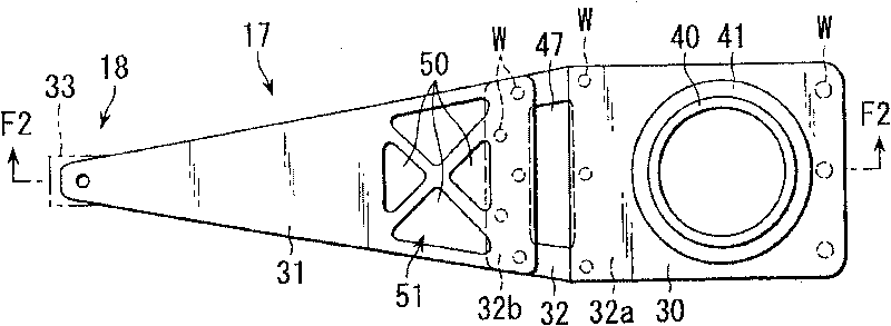
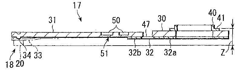
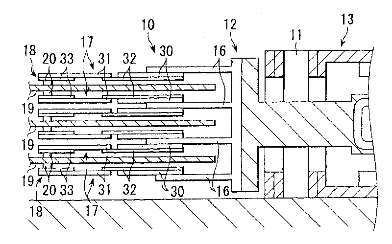
[0027] now refer to Figures 1 to 3 A first embodiment of the present invention is described. image 3 The hard disk drive (HDD) shown includes a bracket 12 which is rotatable about an axis 11 . Carriage 12 is rotated about shaft 11 by a position controlled motor 13, such as a voice coil motor. Mounted on the bracket 12 are arms (actuating arms) 16, suspensions 17 each mounted on each end portion of the arm 16, a head 18 mounted on each end portion of the suspension 17, and the like. When the carriage 12 is driven by the motor 13, the head 18 moves to the desired track of the magnetic disk 19.

[0028] The head 18 includes a slider 20 positioned to face the recording surface of the magnetic disk 19, and a sensor (not shown) fixed to the slider 20. When the disk 19 rotates at high speed, air enters the space between the disk 19 and the slider 20 and rises slightly away from the disk 19, thereby forming an air cushion between the disk 19 and the slider 20.

[0029] Such as ...


PUM

PropertyMeasurementUnit
thicknessaaaaaaaaaa

Abstract

A suspension frame of magnetic disc driver consists of a base, a bear with flexible unit, hinge element for connecting said base with said beam, hole set on beam and cover for covering said hole. It is featured as forming said cover by extended part of extending partial hinge element towards to beam.

Description

[0001] This application is a divisional application of the invention patent application with the filing date of March 29, 2002, the application number of 02107699.5, and the title of "Suspension for Disk Drive". technical field [0002] The present invention relates to a suspension for a disk drive mounted in an information processing device such as a personal computer. Background technique [0003] A hard disk drive (HDD), which is used to record and read information on rotating magnetic or magneto-optical disks, includes a chassis that rotates about an axis. The bracket is rotated around the shaft by a position control motor. The bracket is provided with an arm (actuating arm), a suspension mounted on the end portion of the arm, including the head of the slider mounted on the suspension, and the like. When the disk rotates at high speed, the slider rises slightly on the surface of the disk, thereby forming an air cushion between the disk and the slider. The suspension in...

Claims


Application Information

Patent Timeline
Patent Type & Authority Patents(China)
IPC IPC(8): G11B5/48G11B5/60G11B21/16G11B21/21
Inventor 高木康司半谷正夫入内嶌修藤原哲哉大本亮藏
Owner NHK SPRING CO LTD
Why Eureka
Try Eureka