Fan and plug thereof

A plug and fan technology, applied in the field of fans and their plugs, can solve problems such as reducing the reliability of fan products, achieve the effects of rapid assembly, improve reliability, and avoid interference

Active Publication Date: 2012-10-10
DELTA ELECTRONICS INC
View PDF0 Cites 0 Cited by
  • Summary
  • Abstract
  • Description
  • Claims
  • Application Information

AI Technical Summary

Problems solved by technology

However, since the wire set 11 is connected to the terminal 12 by welding, the redundant wires of the wire set 11 are also likely to interfere in the installation system, reducing the reliability of the fan product

Method used


Image

  • Fan and plug thereof
  • Fan and plug thereof
  • Fan and plug thereof

Examples


Embodiment Construction

[0023] A fan according to a preferred embodiment of the present invention will be described below with reference to related drawings, wherein the same components will be described with the same reference symbols.

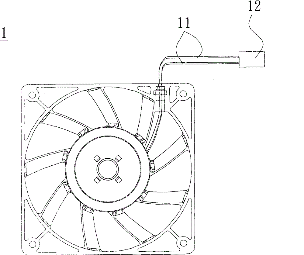
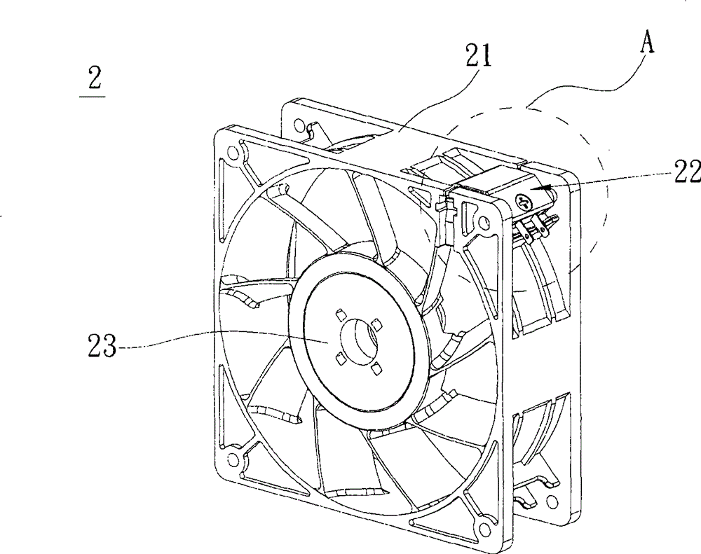
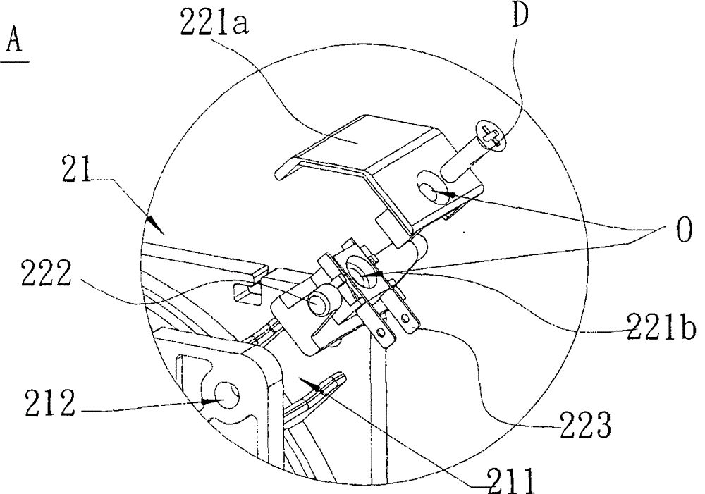
[0024] Please refer to Figure 2A and Figure 2B As shown, a fan 2 according to a preferred embodiment of the present invention includes a fan frame 21 and a plug 22 . The fan 2 can be an axial fan. The fan frame 21 has a receiving portion 211 and two fixing holes 212 on the periphery of the fan frame 21 . The fixing holes 212 are disposed on both sides of the receiving portion 211 . In this embodiment, the fixing holes 212 are disposed on opposite sides of the accommodating portion 211 , but it is not limited thereto.

[0025] The fan plug 22 includes a terminal base 221 having at least two connecting parts 222, an upper base body 221a and a lower base body 221b. The terminal base 222 is accommodated in the accommodating portion 211, and a two-pole blade termina...


PUM


Abstract

The invention provides a fan which comprises a fan frame and a plug. The circumference of the fan frame is provided with a holding part and at least two fixing holes respectively arranged at two sides of the holding part; the plug comprises a terminal seat provided with at least two joint parts and an ambipolar blade terminal clamped and fixed between the terminal seat combined by an upper seat body and a lower seat body; the plug is combined and connected with the fixing hole of the fan frame by the joint parts to hole the plug in the holding part of the fan frame.

Description

technical field [0001] The invention relates to a fan and its plug, in particular to a fan and its plug which can provide fast assembly function and avoid interference when wire groups are assembled. Background technique [0002] As the functions and operating speeds of electronic or mechanical systems increase, the heat generated by them also increases relatively. In order to maintain the normal operation of the system, the existing technology configures a fan for heat dissipation, which is forced to dissipate heat through the airflow, so that the system can be maintained at a normal temperature. operating temperature. [0003] Please refer to figure 1 , an existing fan 1 is connected to an external system through a terminal 12 connected to the end of a wire set 11 . For example, a main board, a circuit board or other mechanical devices (not shown in the figure) are used to receive power and drive signals to operate. However, since the wire set 11 is connected to the ter...

Claims


Application Information

Patent Timeline
Patent Type & Authority Patents(China)
IPC IPC(8): H02K5/22H01R24/66H01R13/73F04D25/06F04D29/00
Inventor 陈典旻庄德财
Owner DELTA ELECTRONICS INC
Why Eureka
Try Eureka