Digital display unit of valve

A digital display and valve technology, applied in the direction of valve device, valve operation/release device, valve details, etc., can solve the problems of inaccurate flow control, inaccurate control mode, unsuitable for popularization and application, etc., and achieve beautiful appearance , Novel product and compact structure

Inactive Publication Date: 2013-03-20
ZHEJIANG WORLD BRASS
View PDF0 Cites 0 Cited by
  • Summary
  • Abstract
  • Description
  • Claims
  • Application Information

AI Technical Summary

Problems solved by technology

[0002] There are two forms of various valves currently on the market: one is that there is no digital display device. When operating this valve, people only use feeling, experience or memory to rotate the valve handle to control the opening or closing of the valve and the flow of liquid. Flow rate, this control method is extremely inaccurate and cannot meet the requirements for precise flow control, resulting in a large loss of energy; second, the digital display device on the valve uses sensors and computer chips to complete the digital display. Although the control method is accurate, the cost is too high, so it is not suitable for popularization and application on commonly used valves.

Method used


Image

  • Digital display unit of valve
  • Digital display unit of valve
  • Digital display unit of valve

Examples


Embodiment 1

[0029] Embodiment 1: see Figure 1-6 :

[0030] The digital display device of the valve includes:

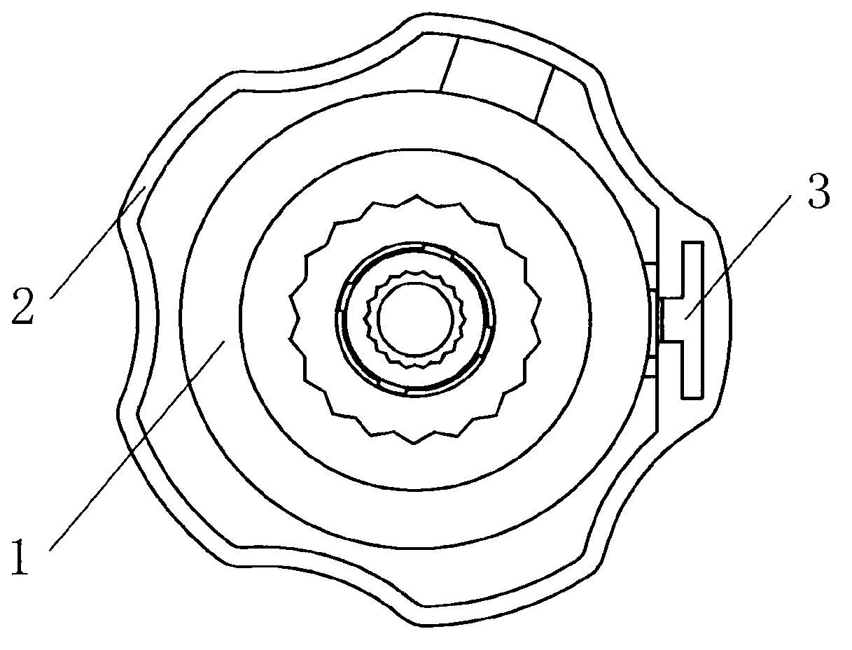
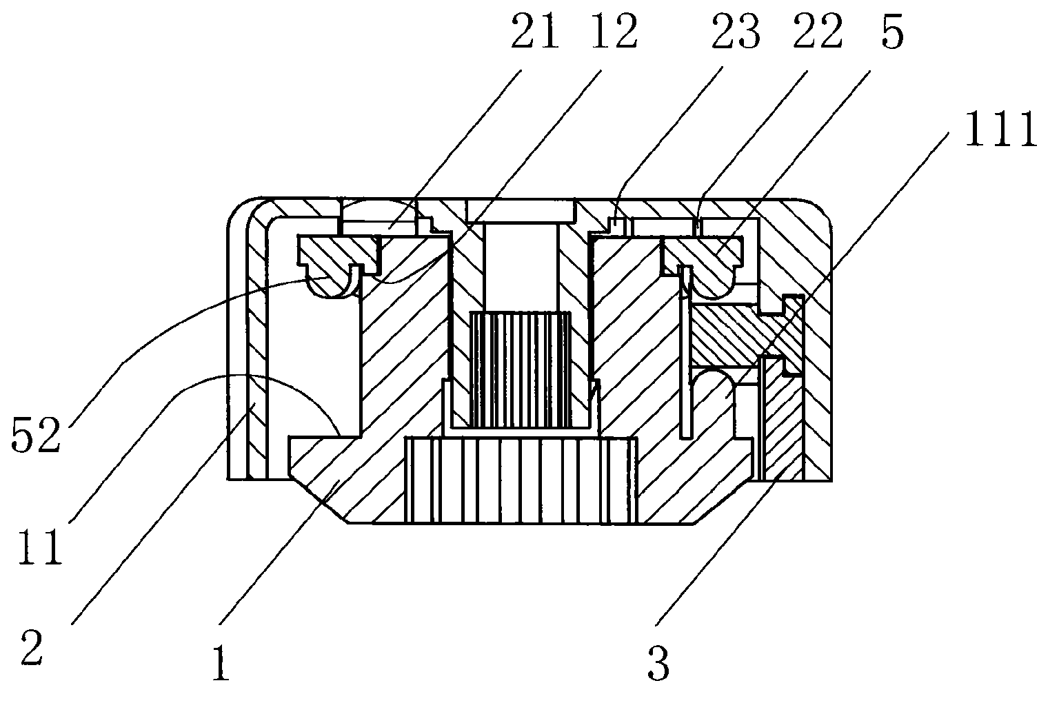
[0031] Base 1: It is a hollow cylinder, an annular lower boss 11 extends outward from the lower part of the outer surface of the base 1, and the upper part of the outer surface of the base 1 shrinks inward to form an annular upper boss 12. 11 is provided with a shifting tooth 111 that can mesh with the gear 7, and a scale and / or scale value 131 for indication is provided on the upper surface 13 of the hollow cylinder;

[0032] Large dial 5: a set of torus set on the upper boss 12 of the base 1, on the upper surface 51 of the torus is provided with a circle of indicating scale and / or scale value 511, on the torus The lower surface is provided with a ring of shifting teeth 52 which can mesh with the gear 7, and the shifting teeth 52 are arranged corresponding to the shifting teeth 111 on the base 1, or in other words, the shifting teeth 52 correspond to the lower boss on the bas...

Embodiment 2

[0038] Example 2: see Figure 7 And reference figure: a digital display valve made with the above-mentioned digital display device of the valve, including a valve housing 92, a valve seat, a valve core and a valve stem 91, the rotation and movement of the valve stem 91 can drive the valve core to the valve The seat implements opening or closing, the base 1 in the digital display device is fixedly connected with the valve housing 92, and the middle connecting seat 28 of the handle housing 2 is fixedly connected with the valve stem 91 controlling the opening of the valve to form a digital display valve.

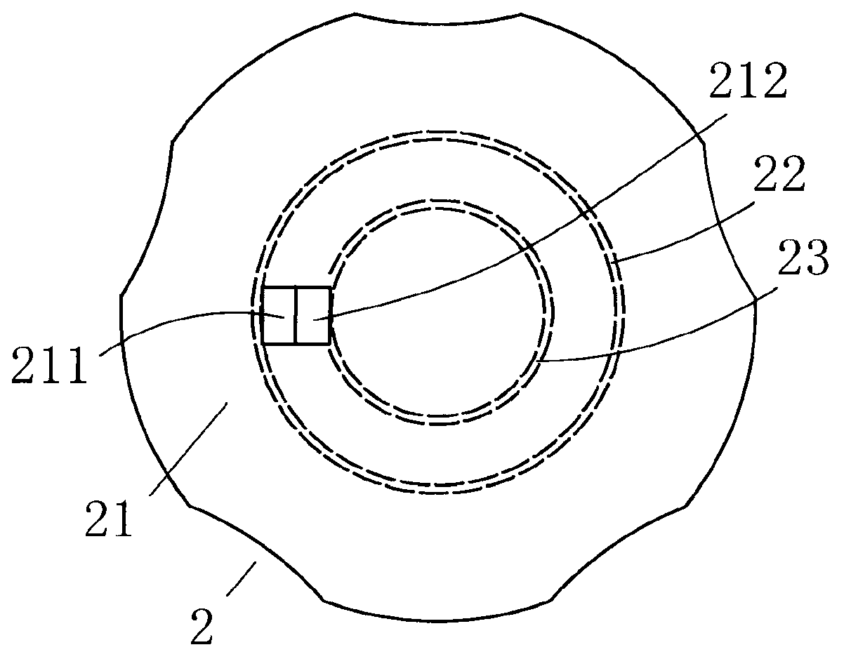
[0039] Use of the present invention: rotate the handle housing 2 counterclockwise, the handle housing 2 drives the control valve stem 91 of the valve, the large dial 5 and the gear 7 to rotate together. The scale 131 and the scale value 132 of the visible part on the upper surface 13 of the base 1 can be observed in the window 212. At this time, the upper surface 51 of the larg...


PUM


Abstract

The invention relates to the valve technical field, namely a valve digital display unit, including a base, wherein a tine meshing with the gear is arranged at the lower part of the outer surface of the base, and a ring of scale and / or scale valve for indication is arranged on the upper surface of the base, an annular boss is formed to contract inwards arranged on the upper part of the outer surface of the base; a large dial, which is a tourus, wherein a scale and / or a scale valve is arranged on the upper surface of the tourus, and a ring of tines meshing with the gear is arranged at the lower part of the tourus; a gear, which is arranged with gear teeth meshing with the tines on the base and the large dial, and the gear is arranged on the side wall of the handle case through the gear shaft; a handle case, the superior wall of which is arranged with a small window for observing the scale and / or the scale valve on the base and the large dial. The invention has the advantages of compact structure, beautiful appearance, accurate figure-reading, convenience, which is suitable for a plurality of valves.

Description

Technical field: [0001] The invention relates to the technical field of valves, in particular to a digital display device for valves. Background technique: [0002] There are two forms of various valves currently on the market: one is that there is no digital display device. When operating this valve, people only use feeling, experience or memory to rotate the valve handle to control the opening or closing of the valve and the flow of liquid. Flow rate, this control method is extremely inaccurate and cannot meet the requirements for precise flow control, resulting in a large loss of energy; second, the digital display device on the valve uses sensors and computer chips to complete the digital display. Although the control method is accurate, the cost is too high, and it is not suitable for popularization and application on commonly used valves. Invention content: [0003] The object of the present invention is to provide a digital display device for a mechanical valve wit...

Claims


Application Information

Patent Timeline
Patent Type & Authority Patents(China)
IPC IPC(8): F16K37/00F16K31/60F16K31/53
Inventor 卓旦春
Owner ZHEJIANG WORLD BRASS
Why Eureka
Try Eureka