Image forming apparatus

An image and page technology, applied in the field of image forming devices, can solve the problems of complex composition, small height difference, poor visual recognition, etc.

Inactive Publication Date: 2012-01-25
RICOH KK
View PDF7 Cites 0 Cited by
  • Summary
  • Abstract
  • Description
  • Claims
  • Application Information

AI Technical Summary

Problems solved by technology

[0008] First, in order to replace the consumables such as the process cartridge and the transfer unit of the image forming unit, although the method of turning and opening the upper unit of the image forming apparatus is adopted, the image reading unit of the upper unit (hereinafter also referred to as "" Scanner") covers the outlet of the paper discharge section, so it will deteriorate the visual recognition
[0009] Second, there is a rotating structure for the upper unit that rotates the paper discharge structure body of consumables such as the process cartridge for replacing the image forming unit or the transfer unit, making it a complicated and cumbersome device
[0010] Therefore, although the transfer unit of the image forming section is also rotated and opened when the unit rotation amount is rotated, if the opening angle is less than a certain degree, it is not easy to carry out consumables such as the process cartridge and the transfer unit of the image forming section. replace
[0011] Third, when the paper discharge outlet is high and the paper discharge flat surface is low, the scanner of the upper unit is located in front of the paper discharge outlet, which hinders the visual recognition of the paper discharge
[0012] Fourth, in order to replace the toner tanks arranged on both sides of the paper discharge part, the scanner of the upper unit and the rotary part unit that rotates with the paper discharge become complicated.
[0013] As for the stacking volume of discharged paper, due to the small inclination during paper discharge and the small height difference between the top of the paper discharge and the paper discharge outlet, it is unfavorable to ensure the stacking volume of discharged paper. In addition, from the front of the device, the Cognition can also be said to be bad
[0014] Fifth, although the toner tank is replaced by sliding the scanner of the upper unit, there is no improvement in the visual recognition of paper discharge
[0028] In the inside-casing and side-discharge type image forming apparatus described in Patent Document 5 (JP-A-2004-264500), the image reading device is supported so as to be slidable in the front-rear direction of the main body frame. The opening window is set in the upper support surface to improve the visual recognition, but it is troublesome to take out the transfer paper from the paper discharge part after winding the hand
[0029] Originally, since the paper discharge port is located below the scanner part constituting the image reading device, and the operation part protrudes, there is convenience (visual recognition, removal Convenience) bad problem

Method used


Image

  • Image forming apparatus
  • Image forming apparatus
  • Image forming apparatus

Examples


Embodiment Construction

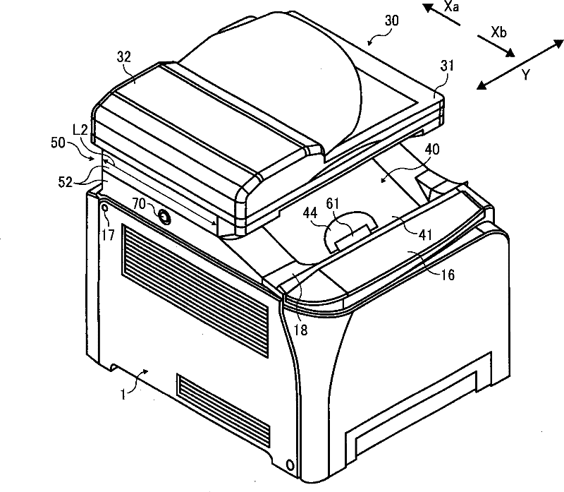
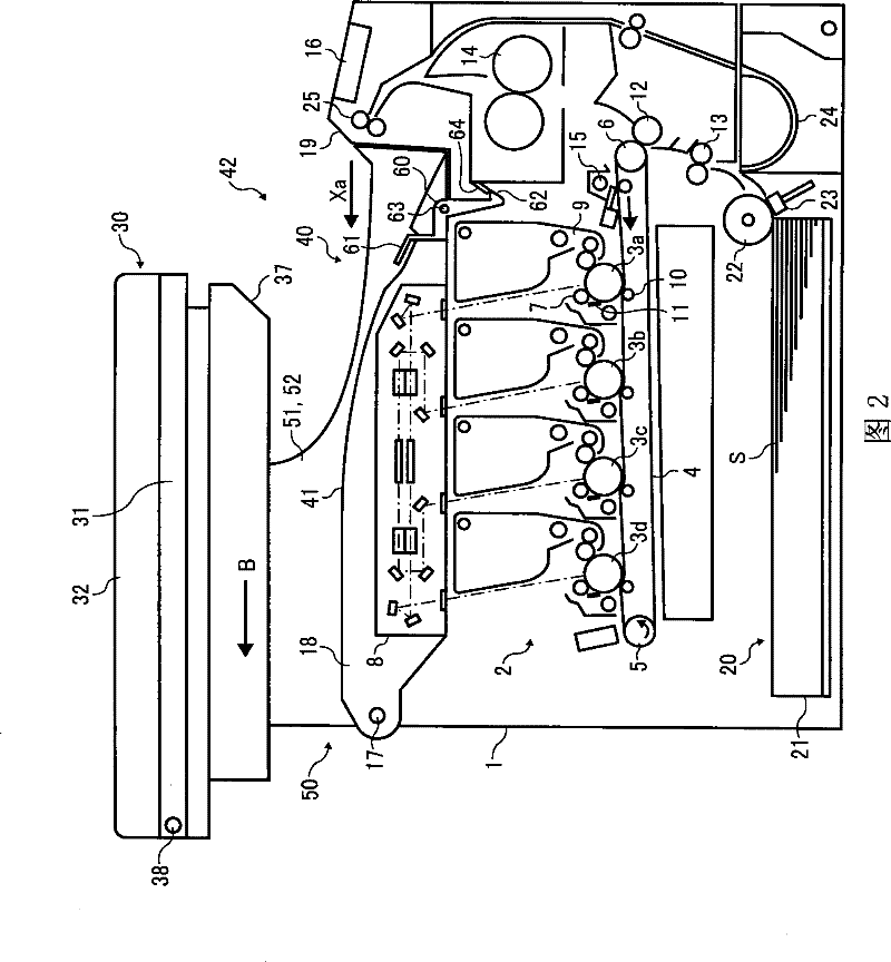
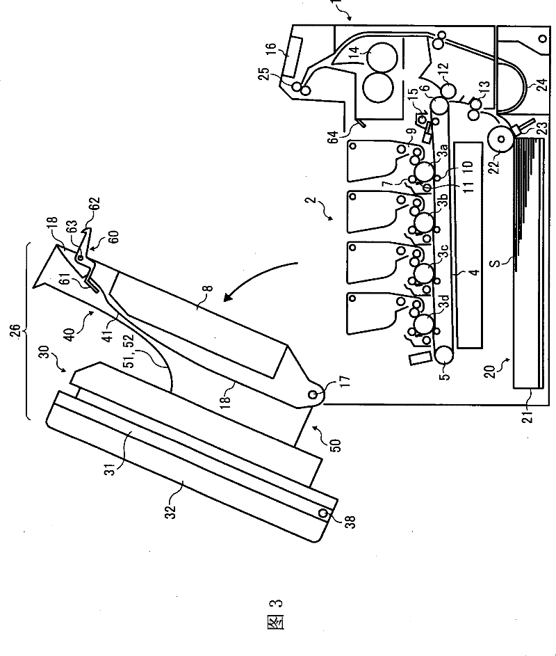
[0097] Hereinafter, embodiments of the present invention including examples will be described in detail based on the drawings. First, refer to figure 1 as well as figure 2 The overall configuration and operation of an image forming apparatus according to an embodiment of the present invention will be described. figure 1 Shown is an external perspective view of an image forming apparatus according to an embodiment of the present invention, figure 2 Shown is a schematic longitudinal sectional view of an example of the internal configuration of the image forming apparatus.

[0098] figure 1 as well as figure 2 The image forming apparatus shown has: an image forming section 2 provided approximately in the center of the apparatus main body 1 and having image forming means for forming an image on a sheet; The paper feeding section 20 of the image forming section 2; the image reading section (hereinafter also referred to as "scanner") provided above the image forming section ...


PUM


Abstract

An image forming apparatus including an image forming section; an upper unit located over the image forming section with a space therebetween and slidable in a direction of from the front side to the rear side of the apparatus and the opposite direction; a sheet discharger for discharging a sheet bearing an image in the first or opposite direction; a sheet stacker receiving the sheet from the sheet discharger; a support arranged outside of both side ends of the sheet stacker in the sheet discharging direction and slidably supporting the upper unit; and a release preventing member for preventing releasing of the upper unit from the support, or a covering member movable from a first position to a second position in conjunction with sliding of the upper unit and covering an opening formedat an end portion of the support when acquiring the first position.

Description

technical field [0001] The present invention relates to image forming apparatuses such as copiers, facsimile machines, printers, typewriters, and multifunction machines having at least two or more of these functions. Background technique [0002] In image forming apparatuses such as copiers, facsimile machines, printers, typewriters, and multifunction machines having at least two or more of these functions, it is known that the upper surface of the apparatus body is set to place and stack sheets on which images are formed. At the same time as the sheet stacking section, an image forming apparatus of the body discharge type (hereinafter referred to as "body discharge type") is disposed in the space above the sheet stacker (see Patent Documents 1 and 2). [0003] Although this type of device has advantages such as a small footprint, it also has problems in visual recognition and paper discharge performance (prevention of paper jams, accumulation volume, etc.) Make sure) exace...

Claims


Application Information

Patent Timeline
Patent Type & Authority Patents(China)
IPC IPC(8): G03G15/00H04N1/00
Inventor 安藤贵之高桥卓二白木孝昌太田佳秀畑山耕治
Owner RICOH KK
Why Eureka
Try Eureka