
Traceroute implementing method and equipment
An implementation method and a routing technology, applied in the field of network communication, can solve problems such as inability to apply trace routing operations, high bandwidth occupation of trace routing, and inability to judge multicast forwarding paths, so as to improve deployability, reduce quantity, and reduce bandwidth resources Effect
- Summary
- Abstract
- Description
- Claims
- Application Information
AI Technical Summary
Problems solved by technology
Method used
Image

Examples
Embodiment 1
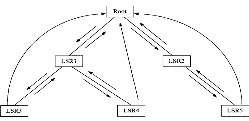
[0072] In this embodiment, the processing process of collecting the topology information of the entire MPLS P2MP LSP by way of trace route is provided, and the topology structure of the entire MPLS P2MP LSP tree is as follows figure 2 shown. exist figure 2 Among them, the MPLS P2MP LSP includes: a root node Root, an intermediate node LSR1, an intermediate node LSR2, a leaf node LSR3, a leaf node LSR4, and a leaf node LSR5.
[0073] refer to figure 2 As shown, the corresponding process of collecting the topology information of the P2MP LSP specifically includes the following steps:
[0074] Step 1, the Root node sends an MPLS echo request message with a TTL value of 1 to its downstream nodes LSR1 and LSR2;
[0075] The root node sets the flag of the leaf node response message in the MPLS echo request message, and the leaf node needs to respond the message to the root node to transmit the information of each node.
[0076] Step 2: After receiving the MPLS echo request mes...
Embodiment 2
[0086]In this embodiment, the whole process of diagnosing the fault point of MPLS P2MP LSP by way of trace route is provided, and in this embodiment, it is assumed that the MPLS P2MP Ping (MPLS point-to-multipoint search) or other means have been known There is a problem with this MPLS P2MP LSP.
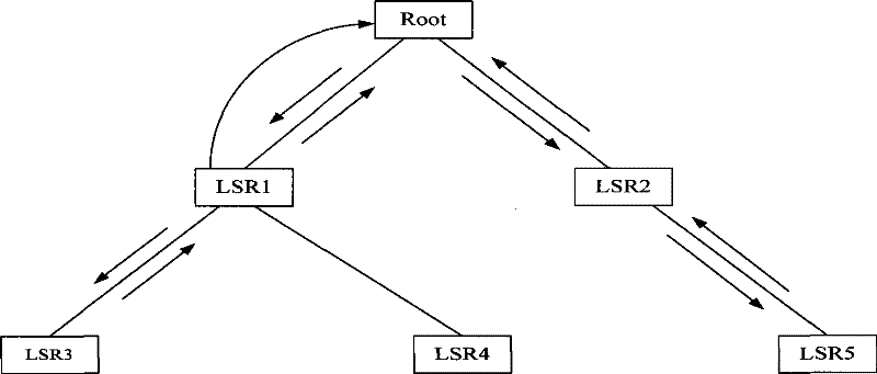
[0087] Such as image 3 As shown, the MPLS P2MP LSP includes: a root node Root, an intermediate node LSR1, an intermediate node LSR2, a leaf node LSR3, a leaf node LSR4, and a leaf node LSR5. refer to image 3 As shown, the process of diagnosing MPLS P2MP LSP failure points for the topology of the entire MPLS P2MP LSP tree may specifically include:
[0088] Step 1, the Root node sends an MPLS echo request message with a TTL value of 1 to the downstream node;
[0089] In the message sent to the downstream nodes LSR1 and LSR2, the flag of the leaf node response message is not set.
[0090] Step 2, after receiving the MPLS echo request message, LSR1 and LSR2 check the forwarding pat...
PUM
 Abstract
Description
Claims
Application Information