Traceroute implementing method and equipment

An implementation method and routing technology, applied in the field of network communication, can solve the problems of large bandwidth occupation of trace routing, inability to judge multicast forwarding paths, inability to apply trace routing operations, etc., so as to improve deployability, reduce quantity, and reduce bandwidth resources. Effect

Inactive Publication Date: 2008-12-31
HUAWEI TECH CO LTD
View PDF0 Cites 32 Cited by
  • Summary
  • Abstract
  • Description
  • Claims
  • Application Information

AI Technical Summary

Problems solved by technology

[0017] Although the above processing scheme can reduce the number of response messages received by the root node, it is only applicable to the P2MP TE LSP in which the intermediate node can obtain the topology structure of the entire tree, and for the P2MP LDP in which the intermediate node cannot obtain the topology structure of the entire tree LSP, because

Method used


Image

  • Traceroute implementing method and equipment
  • Traceroute implementing method and equipment
  • Traceroute implementing method and equipment

Examples


Embodiment 1

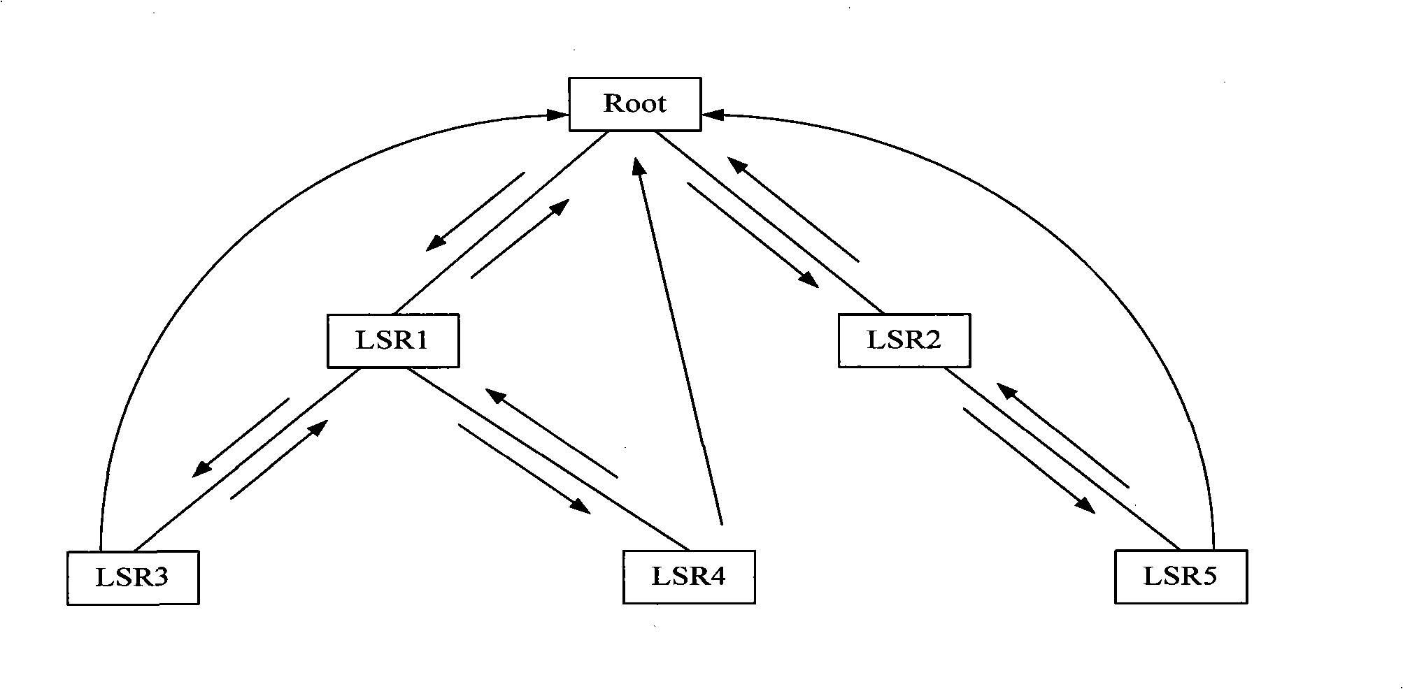
[0072] In this embodiment, the processing process of collecting the topology information of the entire MPLS P2MP LSP by way of trace route is provided, and the topology structure of the entire MPLS P2MP LSP tree is as follows figure 2 shown. exist figure 2 Among them, the MPLS P2MP LSP includes: a root node Root, an intermediate node LSR1, an intermediate node LSR2, a leaf node LSR3, a leaf node LSR4, and a leaf node LSR5.

[0073] refer to figure 2 As shown, the corresponding processing process of collecting the topology information of the P2MP LSP specifically includes the following steps:

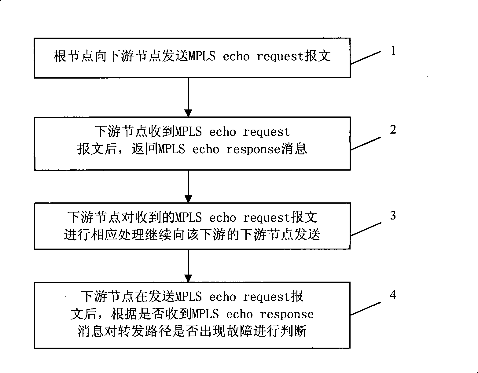
[0074] Step 1, the Root node sends an MPLS echo request message with a TTL value of 1 to its downstream nodes LSR1 and LSR2;

[0075] The root node sets the flag of the leaf node response message in the MPLS echo request message, and the leaf node needs to respond the message to the root node to transmit the information of each node.

[0076] Step 2: After receiving the MPLS echo ...

Embodiment 2

[0086]In this embodiment, the whole process of diagnosing the fault point of MPLS P2MP LSP by way of trace route is provided, and in this embodiment, it is assumed that the MPLS P2MP Ping (MPLS point-to-multipoint search) or other means have been known There is a problem with this MPLS P2MP LSP.

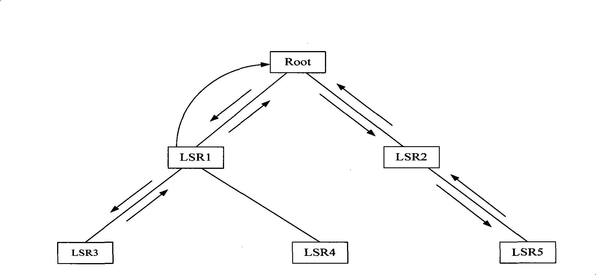
[0087] Such as image 3 As shown, the MPLS P2MP LSP includes: a root node Root, an intermediate node LSR1, an intermediate node LSR2, a leaf node LSR3, a leaf node LSR4, and a leaf node LSR5. refer to image 3 As shown, the process of diagnosing MPLS P2MP LSP failure points for the topology of the entire MPLS P2MP LSP tree may specifically include:

[0088] Step 1, the Root node sends an MPLS echo request message with a TTL value of 1 to the downstream node;

[0089] In the message sent to the downstream nodes LSR1 and LSR2, the flag of the leaf node response message is not set.

[0090] Step 2, after receiving the MPLS echo request message, LSR1 and LSR2 check the forwarding pat...


PUM


Abstract

The invention relates to a realizing method for route tracing and equipment. The method concretely comprises the steps that: first, an initial node sends a request message for route tracing; then, after receiving the request message, an intermediate node returns a response message to a node of a higher level and transmits the request message to a node of a lower level until the request message reaches a leaf node; finally, the node of a higher level realizes the operation of route tracing according to the condition of the received response message. The realization proposal for route tracing provided by the embodiment of the invention can effectively reduce the number of response messages received by the initial node such as a root node, etc., solve the problem that the burden of processing the response messages of the initial node such as the root node, etc., in a multicast tree during the process of route tracing, improve the operation deployability of route tracing and can reduce bandwidth resources occupied by the whole tree during the operating process of route tracing.

Description

technical field [0001] The invention relates to the technical field of network communication, in particular to a technical solution for realizing trace routing operation in a communication network. Background technique [0002] With the development of MPLS (Multiprotocol Label Switching) technology, it has been widely used in multicast. In the MPLS-based multicast solution, RSVP-TE (Resource Reservation Protocol-Traffic Engineering) can be used to establish P2MP LSP (point-to-multipoint multi-protocol label switching path); or, LDP (label distribution protocol) can also be used Establish a P2MP LSP. [0003] In order to ensure the reliability of the P2MP LSP as the MPLS forwarding path, it is necessary to detect the errors of the MPLS forwarding path in time. Usually, a traceroute (trace route) technology can be used to detect and diagnose MPLS forwarding path errors. [0004] Currently, the error detection and diagnosis process for traceroute of P2MP LSP includes: [00...

Claims


Application Information

Patent Timeline
IPC IPC(8): H04L12/56H04L29/06H04L12/44H04L12/701
Inventor 刘淑英
Owner HUAWEI TECH CO LTD
Why Eureka
Try Eureka