Progressive die discharging mechanism

A technology of discharge mechanism and progressive die, which is applied in the direction of ejection equipment, metal processing equipment, forming tools, etc., can solve the problems of high unit price of parts, low production efficiency, and lack of competitiveness, and achieve high-precision fixed distance system, production The effect of improving efficiency and improving competitiveness

Active Publication Date: 2010-02-17
LEMTECH PRECISION MATERIAL (CHINA) CO LTD
View PDF0 Cites 12 Cited by
  • Summary
  • Abstract
  • Description
  • Claims
  • Application Information

AI Technical Summary

Problems solved by technology

For the first method, because it is a side-by-side type, there are more edge materials between the two parts, and the utilization rate of raw materials is low. At the same time, the two parts are discharged from the last station of the mold at the same time, which is easy to occur in the actual production process. mixing phenomenon
For the design of the second method, it is necessary to consider that the two parts can be separated when the material is discharged, so the belt area of ​​the two parts is extended to the edge of the two sides of the material belt, and one of the parts is punched in the mold. The other part is discharged in the final discharge chute of the mold, but its disadvantage is that the excess material belt edge makes the material utilization rate of the part very low, which will inevitably make the unit price of the part very high. For the stamping industry, where the price accounts for more than 60% of the unit price of the parts, such a design is not competitive. In addition, the parts punched out in the mold use the blanking process, so the stamping burrs in the product belt area are different from other parts of the product. On the contrary, the burrs on the part will affect the function of the product
If the design considers that the edge is in the middle, although the utilization rate of the product is improved, the two parts are discharged from the same discharge chute at the same time, and subsequent manual screening is required, which consumes human resources and is easy to mix. , for the third method, because two sets of molds are used, the cost of the mold is nearly doubled, and at the same time, it is necessary to be equipped with two punches, feeders, twice the number of operators, energy consumption, space, etc., and its production relatively low efficiency

Method used


Image

  • Progressive die discharging mechanism
  • Progressive die discharging mechanism
  • Progressive die discharging mechanism

Examples


specific Embodiment approach

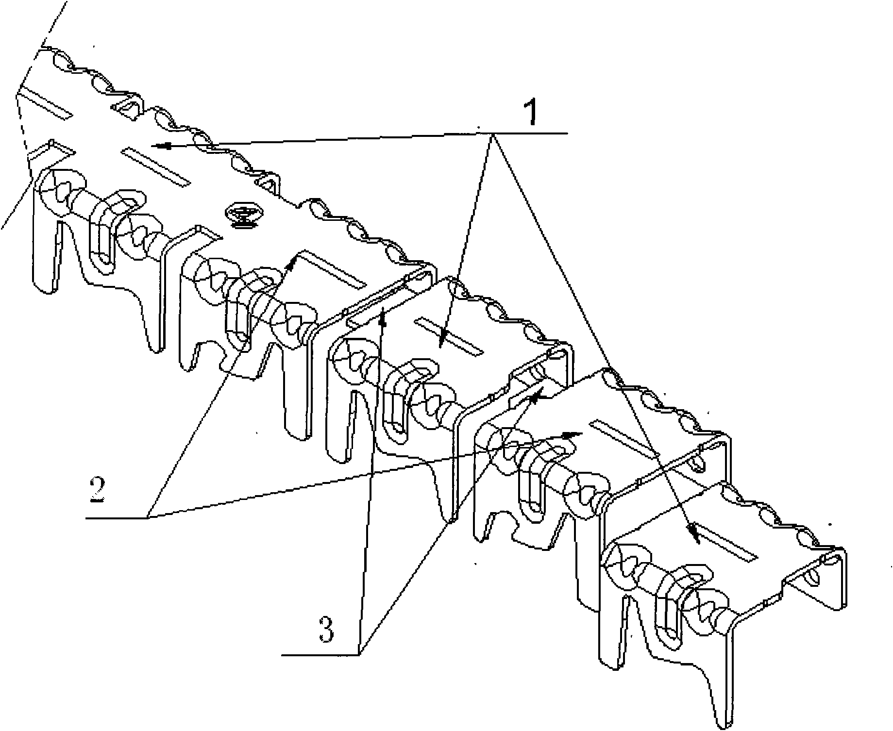
[0030] figure 1 It is a part layout diagram of the products produced by the present invention.

[0031] Such as figure 1 Shown: product a1 and product b2 are two left-right mirror-symmetrical parts, which are transferred through a straight-line middle belt. The material belt passes through a series of punching and cutting in front of the mold to complete all the processes before discharge. , into the progressive die discharge mechanism of the final station.

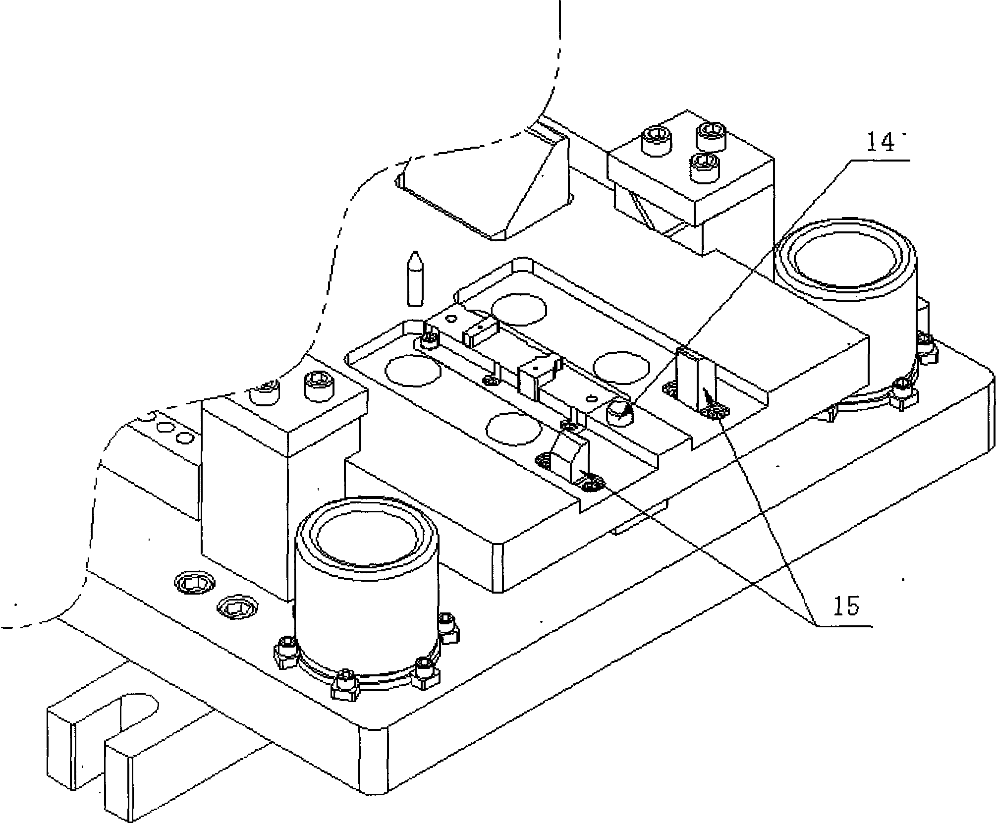
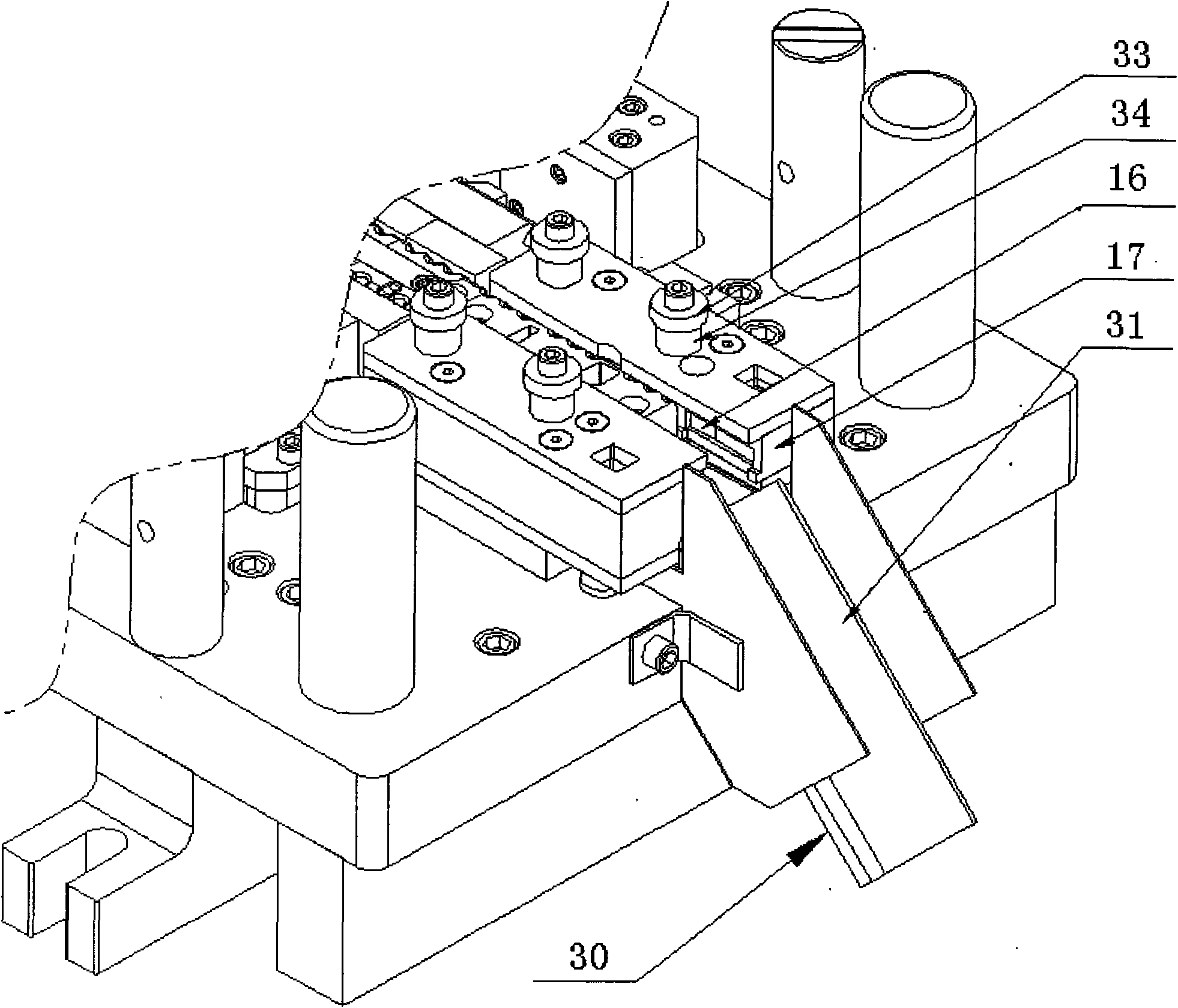
[0032] figure 2 It is a partial view of the upper die of the progressive die of the present invention; image 3 It is a partial view of the lower die of the progressive die of the present invention; Figure 4 It is the opening state figure of the progressive die described in the present invention; Figure 5 It is a closed state diagram of the progressive die of the present invention; Image 6 for Figure 4 Enlarged view of Part A of ; Figure 7 for Figure 5 Enlarged view of Part B of ; Figure 8 For utilizing ...


PUM


Abstract

The invention discloses a progressive die discharging mechanism which comprises two inclined wedges, two groups of movable floating material guiding components and two discharging grooves, wherein thetwo inclined wedges are arranged on an upper die unloading plate, a stripping push rod is arranged between the two inclined wedges, an upper die spring is arranged behind the stripping push rod, andan upper die insert is arranged at the back side of the spring; the two groups of movable floating material guiding components are arranged at two sides of a material belt of a lower die, a lower dieinsert is arranged below the floating material guiding components, the lower die insert is positioned in a die cavity of a lower die plate, two guiding poles are arranged between each the floating material guiding component and the lower die insert, and gaskets are arranged at the upper ends of the guiding poles; and the two discharging grooves are arranged at the discharging point and are respectively positioned outside and inside the progressive die. Parts produced by the progressive die discharging mechanism can not generate the material mixing phenomenon, and the burrs of two types of parts are positioned at the same preset side, thus the using functions of products can not be influenced. In addition, the progressive die discharging mechanism improves the utilization ratio of materialsand simultaneously has high-precision guide and an accurate distance detecting system, thereby greatly improving the production efficiency, reducing the unit price of parts and improving the market competitiveness.

Description

technical field [0001] The invention relates to a discharge mechanism of a stamping die, and more specifically relates to a discharge mechanism of a progressive die with one discharge and two straight rows in the middle with material layout design. Background technique [0002] There are three main design methods for some stamping products on the market, especially some parts with left-right symmetry or parts with a large production volume: the first is to design the strips side by side, one out of two; The second is to design the strips in a straight row, one out of two; the third is to open a set of molds for production. For the first method, because it is a side-by-side type, there are more edge materials between the two parts, and the utilization rate of raw materials is low. At the same time, the two parts are discharged from the last station of the mold at the same time, which is easy to occur in the actual production process. mixing phenomenon. For the design of the...

Claims


Application Information

Patent Timeline
Patent Type & Authority Applications(China)
IPC IPC(8): B21D37/12B21D45/04
Inventor 李配宇
Owner LEMTECH PRECISION MATERIAL (CHINA) CO LTD
Why Eureka
Try Eureka