Magnetic connector for headset

A magnetic connector, connector technology, applied in the direction of connection, conductive connection, electrical component connection, etc., can solve problems such as difficulty in the acoustic performance of receivers and microphones

Active Publication Date: 2010-03-31
APPLE INC
View PDF7 Cites 19 Cited by
  • Summary
  • Abstract
  • Description
  • Claims
  • Application Information

AI Technical Summary

Problems solved by technology

Achieving ideal receiver and microphone acoustic perfor

Method used


Image

  • Magnetic connector for headset
  • Magnetic connector for headset
  • Magnetic connector for headset

Examples


Embodiment Construction

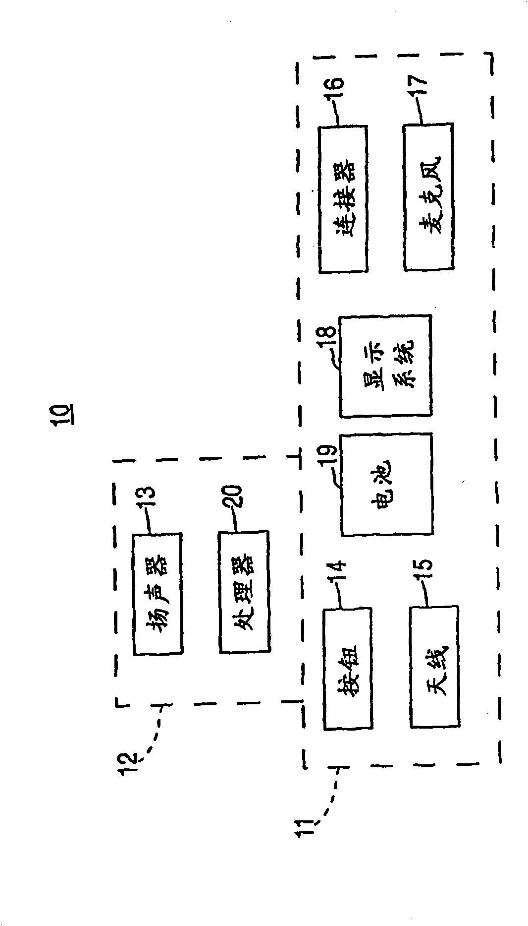
[0097] The present invention relates to earphones and methods of manufacture thereof. A headset is a communication device worn on a user's head for hands-free data and / or voice communication with a host device such as a computer, telephone headset, cell phone, automobile, or the like. Headphones may include one or more speakers (in the vicinity of one or both ears) for audio output and / or one or more microphones for audio input.

[0098]Headphones can take a variety of different form factors or shapes. In some cases, the headset may be implemented as an earpiece that acts as the primary support mechanism for wearing the headset. For example, the earphones may be supported on the head with earpieces worn on or inserted into the ears. Alternatively, the headset may be supported by a frame or strap that fits over the user's head. The headset may include a fixed or movable boom that places the microphone close to the user's mouth (around the face). Alternatively, the headset m...


PUM

PropertyMeasurementUnit
Widthaaaaaaaaaa
Widthaaaaaaaaaa
Widthaaaaaaaaaa

Abstract

The invention relates to a magnetic connector for a headset. Headset assemblies and headset connectors are provided. Headset connectors can include a magnetic mating face and a plurality of electricalcontacts disposed within the mating face. Engaging assemblies and engaging connectors are also provided. The engaging connectors can include a housing having a mating side, a magnetic array structure, and a plurality of spring biased contact members. The magnetic array structure can be fixed within the housing and house a plurality of spring biased contact members. The spring biased contact members can include tips that extend out of the mating side. The tips can electrically couple with electrical contacts in a headset connector.

Description

[0001] Cross References to Related Applications [0002] This application claims priority to the following co-pending, commonly assigned U.S. Provisional Patent Applications, namely: Application No. 60 / 879,177, filed January 6, 2007; Application No. 60 / 879,193; Application No. 60 / 879,195 filed January 6, 2007; all of which are hereby incorporated by reference. [0003] Commonly assigned U.S. Patent Application No. 11 / 235,873, entitled "Electromagnetic Connector for Electronic Devices," filed September 26, 2005, by DiFonzo et al. (Attorney Docket No. P3794US1 / 119-0060US.1), which application is incorporated herein by reference in its entirety. [0004] Commonly assigned U.S. Patent Application No. 11 / 235,875, filed September 26, 2005, by Rohrbach et al., entitled "Magnetic Connector for Electronic Device" (Attorney Docket No. .P3593US1 / 119-0060US), the entire content of which application is incorporated herein by reference. [0005] Commonly assigned U.S. Patent Application ...

Claims


Application Information

Patent Timeline
IPC IPC(8): H01R11/30H01R13/62H04M1/60H04W52/02
CPCH04R1/1016H01R13/2428H01R13/64H01R29/00H05K1/147H04M1/0277H04M1/05H04R2201/105H01R13/6205H05K1/189H04M1/0262H01R13/7039H04M2250/02H04R1/1025H05K2201/05H05K1/028H04W52/0274H04R1/1058H04B2001/3866H01R43/26H04M1/0274H04M1/6058H04R2420/07H04M1/6066H01R13/02H01R13/62Y02D30/70H02J7/00H04R25/603H04R25/556H04R25/558H04R25/602H02J7/0042H04R1/1041H04R1/105H04R2201/107H04R2420/09
Inventor M·E·汉基E·A·桑福德C·D·普雷斯特W·C·利姆
Owner APPLE INC
Why Eureka
Try Eureka