

High-efficiency energy-saving horizontal self-sucking pump
A high-efficiency, energy-saving, self-priming pump technology, used in non-variable-capacity pumps, pumps, drive pumps, etc., can solve problems such as reducing pump efficiency, and achieve the effect of reducing volume loss
Inactive Publication Date: 2010-07-21
陆波
View PDF5 Cites 7 Cited by
- Summary
- Abstract
- Description
- Claims
- Application Information
AI Technical Summary
Problems solved by technology
Method used
View moreImage
Smart ImageViewing Examples

Examples
Embodiment Construction
[0012] The following examples are used to illustrate the present invention, but are not used to limit the scope of the present invention, all equivalent technical solutions also belong to the category of the present invention, and the patent protection scope of the present invention should be defined by each claim.
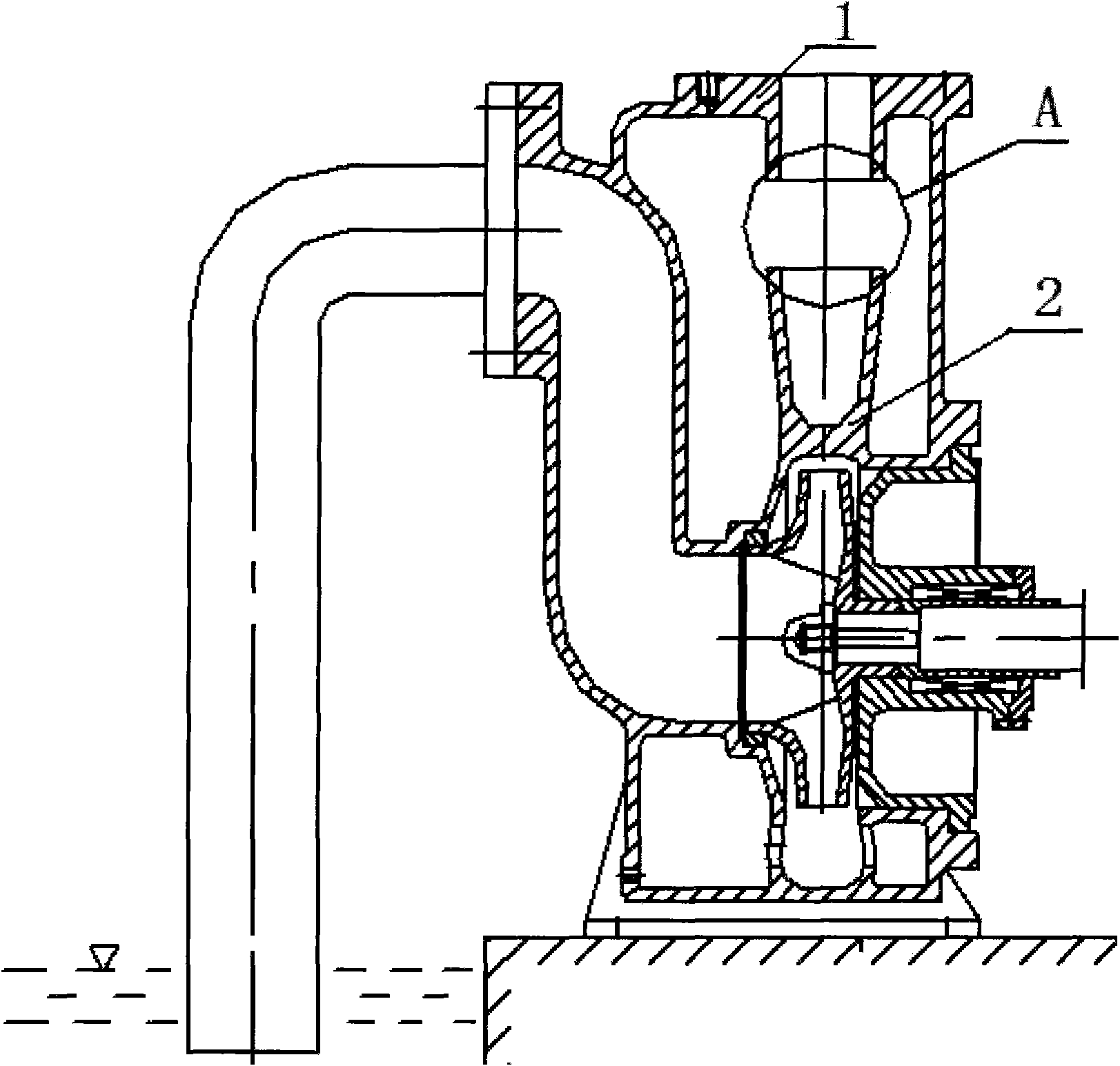
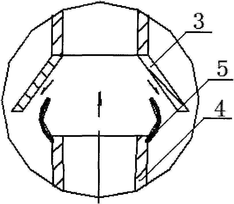
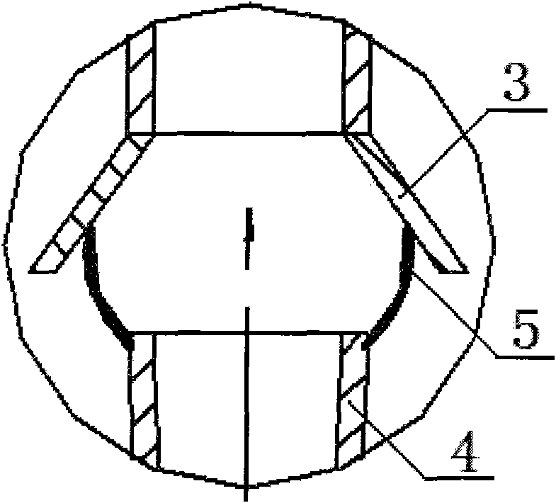
[0013] From Figure 1 to Figure 3 It can be seen from the figure that a high-efficiency energy-saving horizontal self-priming pump includes a pump body 1 and a pump casing 2. The pump body 1 and the pump casing 2 are integrated, and it is characterized in that: at the outlet of the pump body 1 A flexible material sleeve 5 is arranged on the pipe 3 and the outlet end 4 of the pump casing 2 .
Login to View More PUM
 Abstract
The invention relates to a high-efficiency energy-saving horizontal self-sucking pump which comprises a pump shell and a pump body, wherein the pump shell and the pump body are formed into a whole, and a flexible material sleeve is arranged on the outlet pipe of the pump body and at the outlet end of the pump shell. When the self-sucking pump is started for vacuum pumping, water can reflow through a gap between the outlet end of the pump shell and the outlet pipe of the pump body to implement a vacuum pumping starting program; when the self-sucking pump normally works, because water pressure is increased, the impulsive force generated by discharged water enables the upper part of the flexible material sleeve at the outlet end of the pump shell to be enlarged and extruded together with the outlet pipe of the pump body to generate a sealing action, and the continuous reflow of the water is blocked, thereby reducing the volume loss of the self-sucking pump and improving the water pump efficiency by 5-8 percent.
Description
technical field [0001] The invention relates to a horizontal self-priming pump. Background technique [0002] The working principle of the horizontal self-priming pump is: before the self-priming pump is started, the pump chamber is filled with water. After the pump is started, the impeller rotates at a high speed to make the water in the impeller flow channel drain out of the volute, so that the pump inlet forms a vacuum, and the water in the suction pipe Air enters the pump, mixes with the water in the pump chamber, and is discharged to the gas-liquid separation chamber on the upper part of the pump chamber through the impeller. Due to the sudden increase of the outlet area, the air and water are separated, and the separated air is discharged through the pump outlet pipe, and the separation Due to its high specific gravity, the water that comes out sinks and flows to the outer edge of the impeller through the return hole at the bottom of the pump casing, and continues to m...
Claims
Login to View More Application Information
Patent Timeline
 IPC IPC(8): F04D9/02
Inventor陈怀玉孙权
Owner陆波