Magazine moving device of brush type street sweeper truck

A mobile device and cleaning vehicle technology, which is applied to road cleaning, cleaning methods, construction, etc., can solve the problems of complex processing, long piping distance, and heavy weight, etc., and achieve the effect of simple processing

A mobile device and cleaning vehicle technology, which is applied to road cleaning, cleaning methods, construction, etc., can solve the problems of complex processing, long piping distance, and heavy weight, etc., and achieve the effect of simple processing

CN101818488AActive Publication Date: 2010-09-01HOWA MASCH LTD

Image

  • Magazine moving device of brush type street sweeper truck
  • Magazine moving device of brush type street sweeper truck
  • Magazine moving device of brush type street sweeper truck

Examples


Embodiment Construction

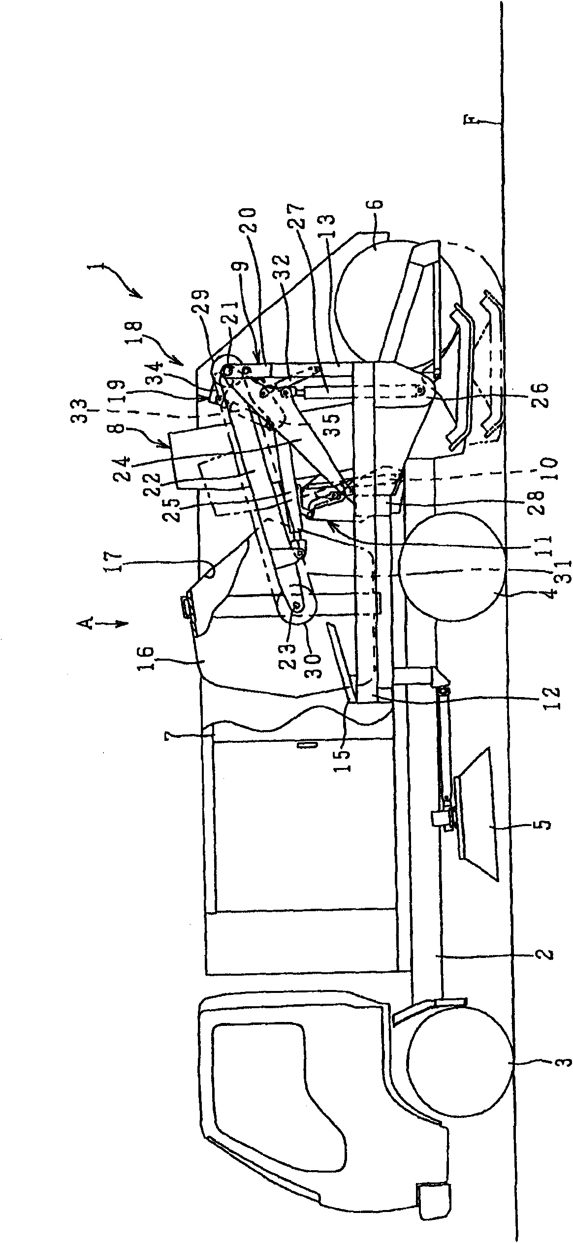
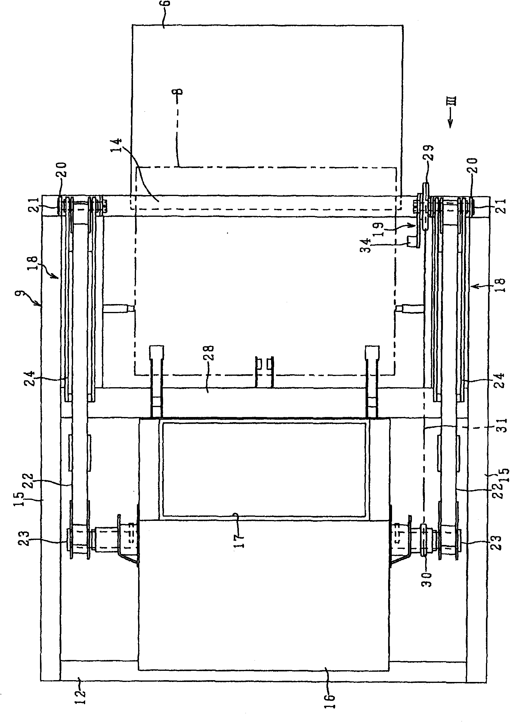
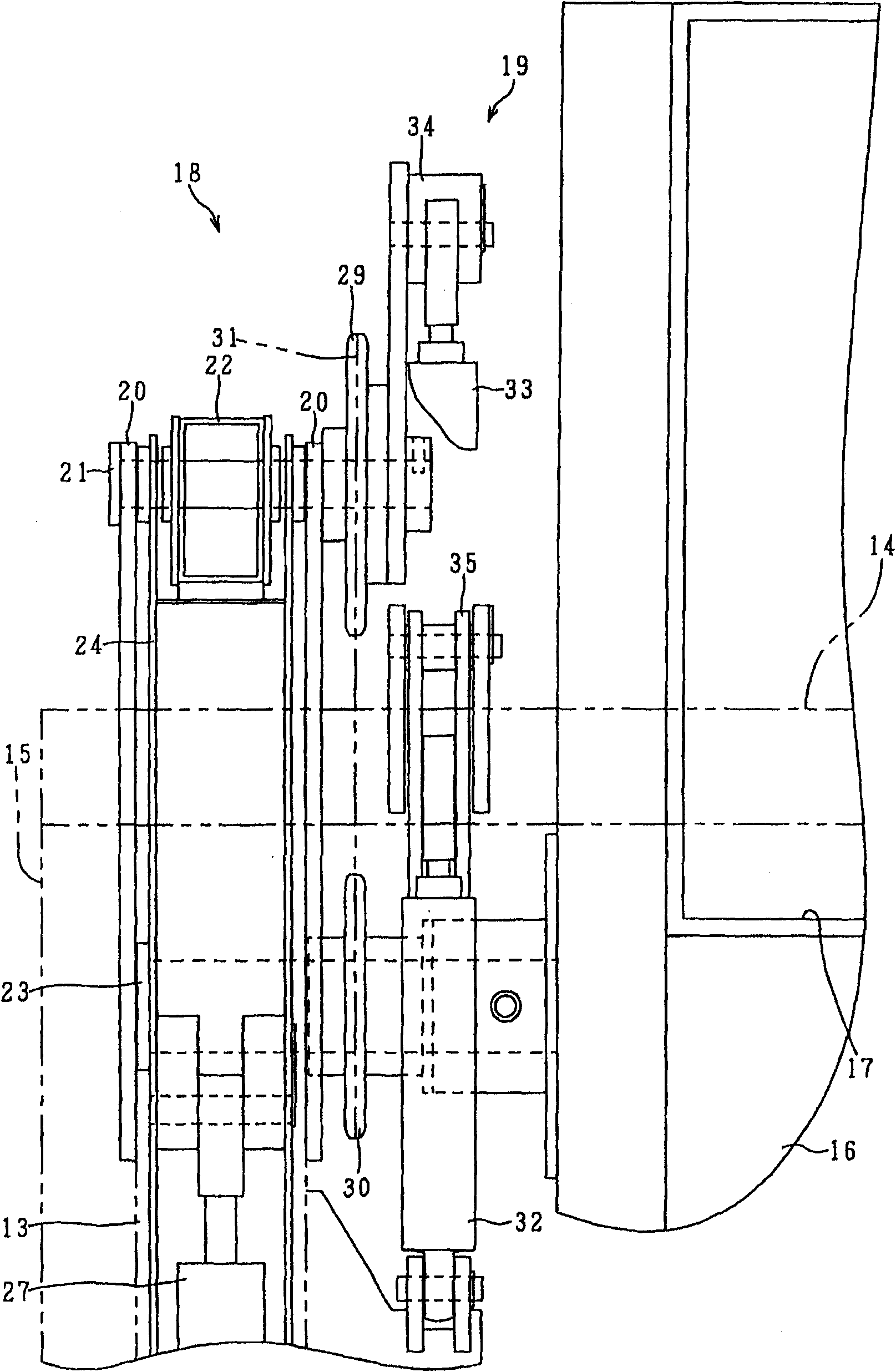
[0033] pass Figure 1 to Figure 9 Embodiments of the present invention will be described. The brush-type road sweeper 1 is provided with a pair of side brushes 5, 5 rotatably and movable up and down on the left and right sides of the chassis 2, between the front and rear wheels 3, 4, and on the other hand, the main brush is arranged behind the chassis 2. 6. Sweep the dust collected by the side brushes 5 and 5 on the road surface F in the lower center of the chassis 2 through the main brush 6 to the front side and upward. Reference numeral 7 denotes a cover covering the upper, left, and right sides of the chassis 2 and the upper part of the main brush 6 . The main brush 6 is rotatably assembled behind the lower end of the conveyor device 8 disposed in front of it in a vertical posture, and the dust swept up is conveyed upward by the conveyor device 8 . The conveyor device 8 is also as figure 1 As shown, it is a structure in which the support frame 9 integrally assembled to t...


PUM


Abstract

A magazine moving device of brush type street sweeper truck. A magazine (16) is arranged to move between a dust recovery position on a chassis and a dust discharge position (B) where the dust can be discharged by a lift arm (22). A chain (31) is hung between a first sprocket wheel (29) arranged on a base end of the lift arm (22) and a second sprocket wheel (30), integrated with the magazine (16), arranged at the side of the lift arm (22) near the magazine (16), a pressure cylinder (32, 33) arranged on a support framework (9) is connected on a first sprocket wheel (29). In the dust discharge position (B), the magazine (16) is rotated by the pressure cylinder (32, 33) through first and second sprocket wheels (29, 30) and the chain (31). The pressure cylinder )32, 330 is arranged on the support framework (9), thus a pipe to the pressure cylinder is processed simply and the magazine side is changed to be light.

Description

technical field [0001] The present invention relates to a brush that moves a hopper between a dust recovery position capable of recovering dust and a dust discharge position capable of discharging dust on a chassis, and is capable of discharging dust from the hopper at the dust discharge position The bucket mobile device of the type road sweeper. Background technique [0002] The structure described in Unexamined-Japanese-Patent No. 2008-285928 (henceforth "patent document 1") is known about the bucket moving apparatus of a brush-type road sweeper. It rotates the lift arm by extending the 1st and 2nd cylinders, and the bucket is placed on the chassis at the dust collection position in front of the conveyor device. It moves to the rear of the car body through the conveyer device and the upper part of the main brush. At this time, there is a first sprocket coaxially fixed to the fulcrum shaft of the pillar erected on the chassis, and a first sprocket with a diameter ratio co...

Claims


Application Information

Patent Timeline
01 Sep 2010
Publication
CN101818488A
IPC
E01H1/05
Inventors
舟桥弥典