Phase lock loop circuits

一种锁相环、电路的技术,应用在电气元件、功率的自动控制等方向,能够解决低KVCO等问题,达到面积节省的效果

Inactive Publication Date: 2010-11-03
MEDIATEK INC
View PDF8 Cites 15 Cited by
  • Summary
  • Abstract
  • Description
  • Claims
  • Application Information

AI Technical Summary

Problems solved by technology

In order to overcome process changes and adapt to the output frequency of GHz level, it is impossible to obtain low KVCO, and KVCO inevitably reaches the range of several GHz / Volt

Method used


Image

  • Phase lock loop circuits
  • Phase lock loop circuits
  • Phase lock loop circuits

Examples


Embodiment Construction

[0016] Certain terms are used in the description and claims to refer to particular elements. Those skilled in the art should understand that hardware manufacturers may use different terms to refer to the same component. The specification and claims do not use the difference in name as a way to distinguish components, but use the difference in function of components as a criterion for distinguishing. The "comprising" mentioned throughout the specification and claims is an open term, so it should be interpreted as "including but not limited to". In addition, the term "coupled" herein includes any direct and indirect means of electrical connection. Therefore, if it is described that the first device is coupled to the second device, it means that the first device may be directly electrically connected to the second device, or indirectly electrically connected to the second device through other devices or connection means.

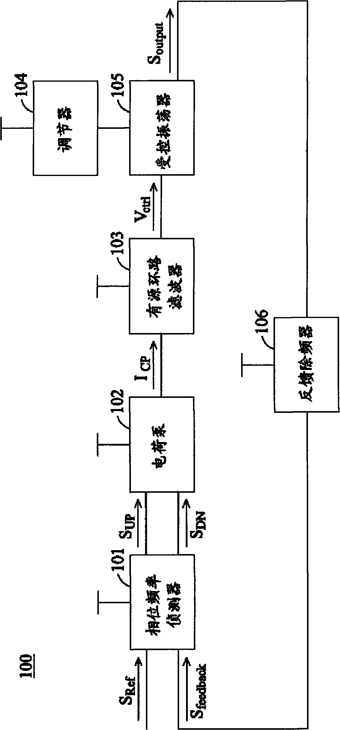
[0017] figure 1 A schematic diagram of a phase locked ...


PUM


Abstract

A phase lock loop circuit is provided. A phase frequency detector detects a phase difference between a feedback signal and a reference signal, and generates a phase error signal in response to the detected phase difference. A charge pump consists of at least one core device and outputs a current signal based on the phase error signal. An active loop filter receives and transfers the current signal into a control signal. Operating voltage of the active loop filter is higher than operating voltage of the charge pump. A controlled oscillator receives the control signal and generates an output signal in response to the control signal. A feedback divider receives the output signal to generate the feedback signal. The area is saved and operation is performed at high speed by using the charge pump using the core device, the active loop filter and the controlled oscillator in the phase lock loop circuit.

Description

technical field [0001] The present invention relates to a phase lock loop circuit (Phase Lock Loop, PLL) circuit, more particularly, relates to a PLL circuit that can save circuit area and has low KVCO. Background technique [0002] PLL stands for Phase Locked Loop and is basically a closed loop frequency control system in which operation is based on phase sensitive detection of the phase difference between a feedback signal and a reference signal. The PLL circuit responds to both frequency and phase input signals, which automatically raises or lowers the frequency of the controlled oscillator until the frequency and phase of the feedback signal match the reference signal. Simply put, a PLL compares the frequencies of two signals to generate a control signal that is proportional to the difference between the two input frequencies. The control signal is used to drive a controlled oscillator (controlled oscillator), such as a voltage-controlled oscillator (Voltage-Controlled ...

Claims


Application Information

Patent Timeline
Patent Type & Authority Applications(China)
IPC IPC(8): H03L7/099
CPCH03L2207/06H03L7/093H03L7/099H03L7/0893
Inventor 刘学欣
Owner MEDIATEK INC
Why Eureka
Try Eureka