Drive axle for electric vehicle or hybrid electric vehicle

A technology for hybrid electric vehicles and electric vehicles, which is applied to the layout of multiple different prime movers of electric vehicles and general power plants, electric power plants, etc., and can solve the problems of poor economic benefits and competitiveness, poor vehicle endurance, and inappropriate and other problems, to achieve the effect of compact structure, high universal rate and long service life

Active Publication Date: 2013-05-08
CHONGQING CHANGAN AUTOMOBILE CO LTD
View PDF0 Cites 0 Cited by
  • Summary
  • Abstract
  • Description
  • Claims
  • Application Information

AI Technical Summary

Problems solved by technology

[0002] The development of electric vehicles has a history of nearly a hundred years, and hybrid vehicles have also undergone decades of development, but whether it is strong hybrid, medium hybrid, weak hybrid technology, or pure electric technology, they are basically based on The power transmission mechanism is arranged on the basis of the chassis frame of the vehicle, especially the design of the suspension mechanism and the power output structure of the vehicle is almost unchanged, so that the technology of electric vehicles and hybrid vehicles is not integrated in the design. The advantages of the vehicle are maximized, especially its vehicle suspension and its power output mechanism, which are often directly adopted from the design of old vehicles
Since the various functional parts of the old-fashioned suspension and its power output mechanism, such as shock absorption, steering, driving and other parts, have a certain separation in function, it will cause the entire structure to occupy a large space, so This mechanism is not suitable for electric and hybrid vehicles, especially when the energy density of batteries is still relatively low. The worse it is, the worse the economic benefit and competitiveness of the vehicle

Method used


Image

  • Drive axle for electric vehicle or hybrid electric vehicle
  • Drive axle for electric vehicle or hybrid electric vehicle
  • Drive axle for electric vehicle or hybrid electric vehicle

Examples


Embodiment Construction

[0014] The present invention will be further described below in conjunction with the accompanying drawings.

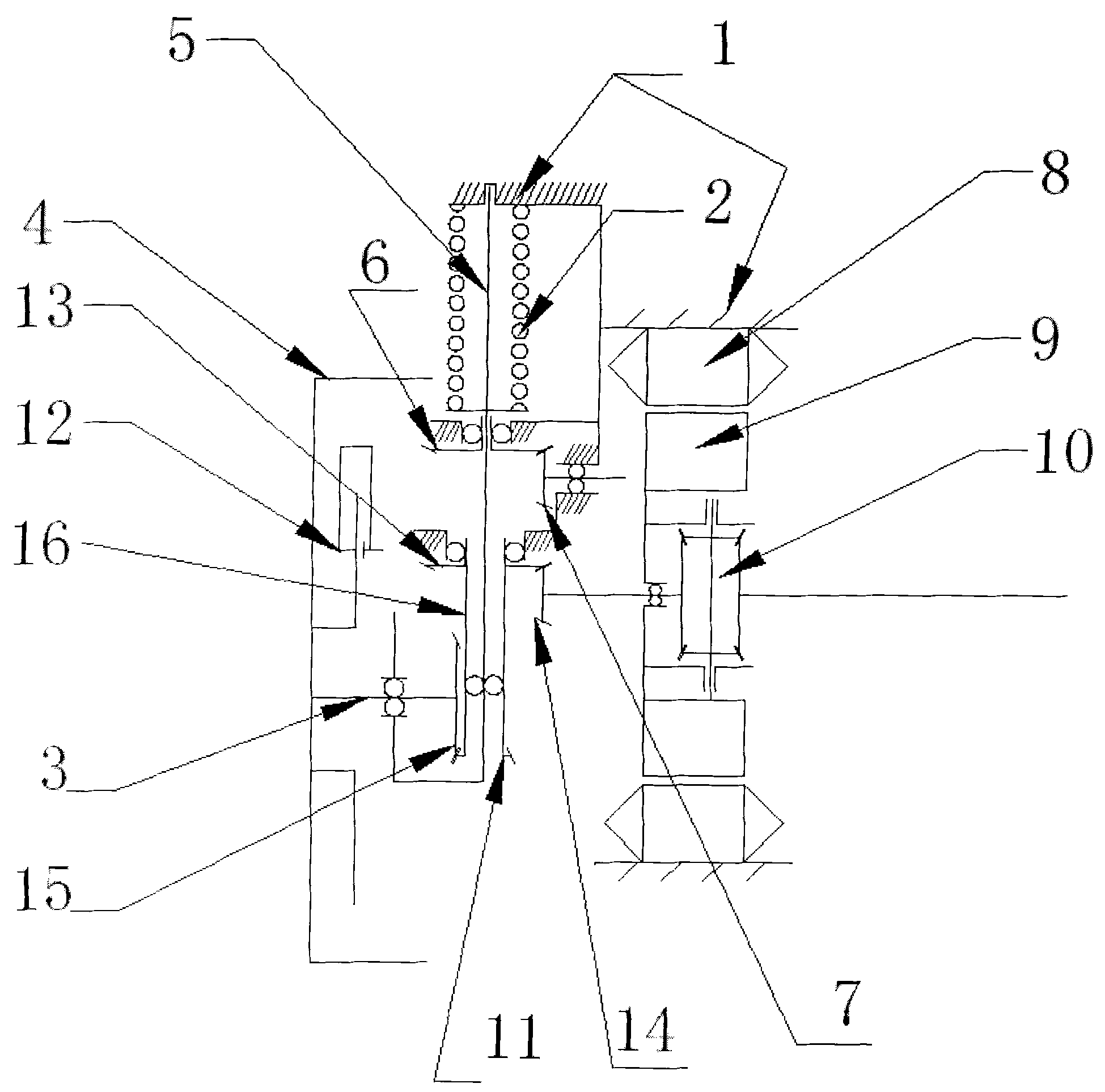
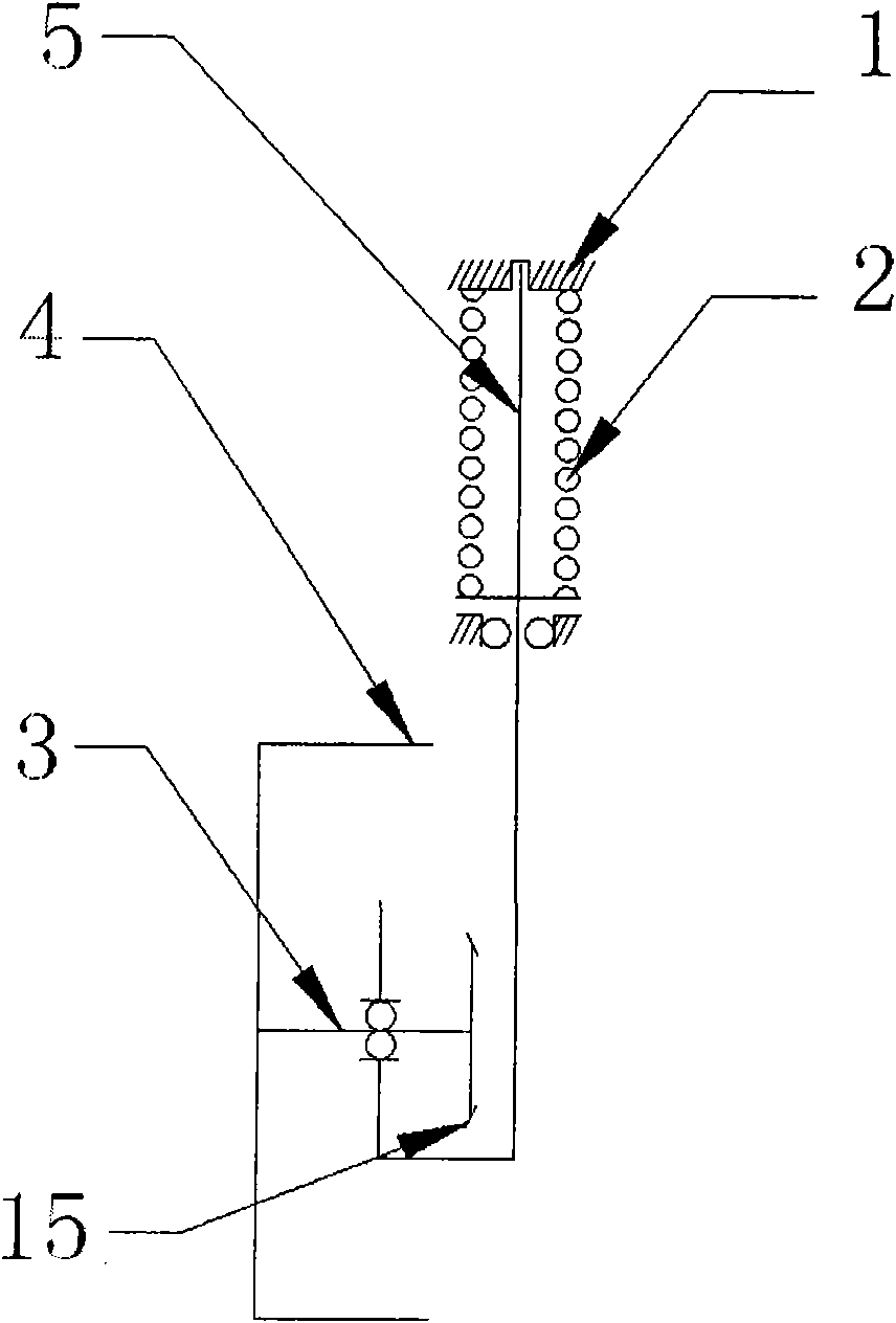
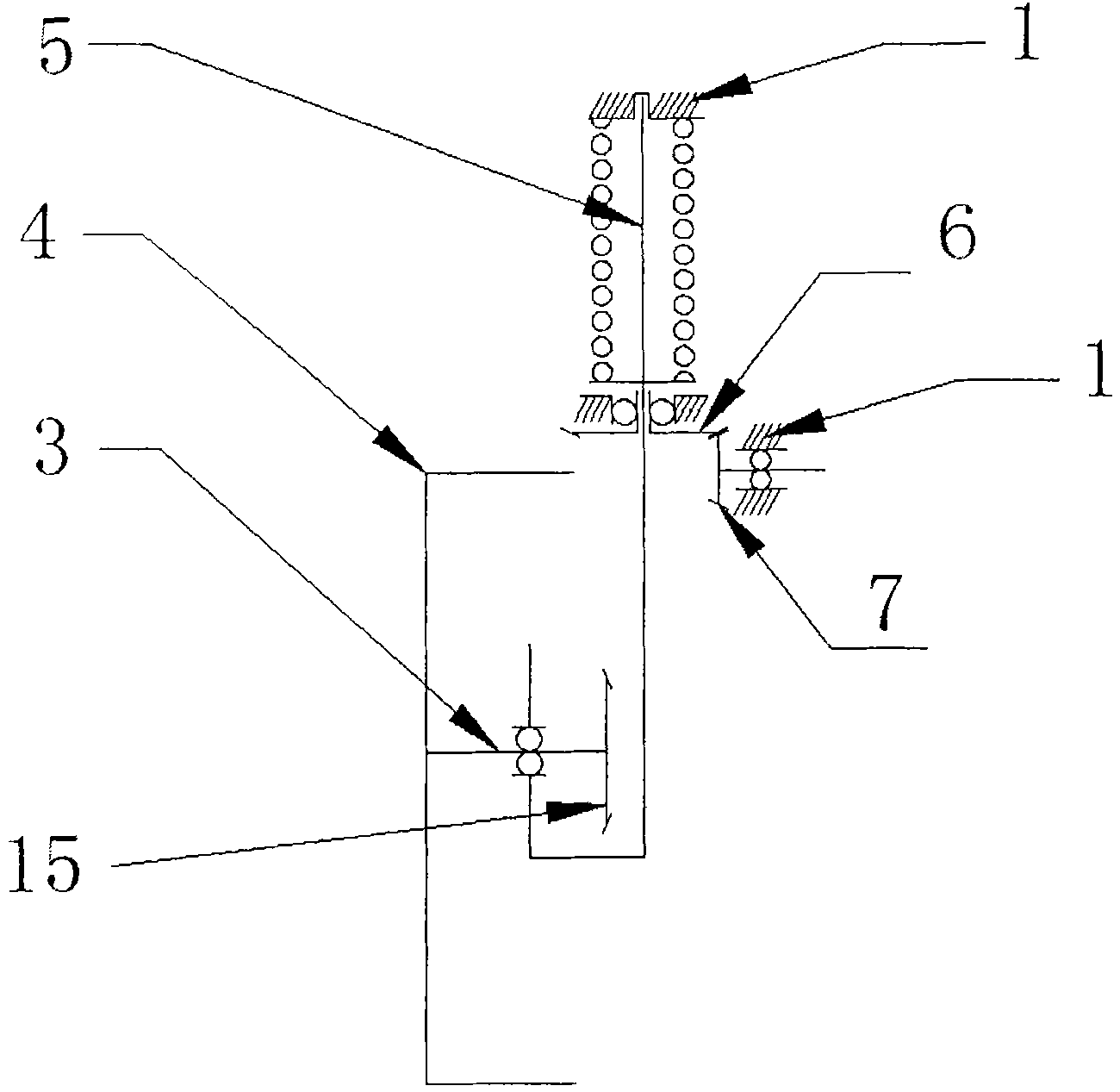
[0015] see figure 1 The drive axle shown for an electric vehicle or a hybrid vehicle includes a motor stator 8 fixed on the vehicle body 1, a motor rotor 9 corresponding to the motor stator, a differential 10 fixedly connected to the motor rotor, The driving bevel gear 14 on the output end of the half shaft that is arranged on the axle shaft that is connected with the differential, the damping steering shaft 5 that the upper end cooperates with the car body 1 and the middle part cooperates with the bearing on the car body, and is sleeved on the damping steering shaft. One end of the upper part of the shaft is close to the car body 1, and the other end is close to the shock absorbing spring 2 arranged on the spring seat on the shock absorbing steering shaft, and the steering input conical gear 7 that is connected with the steering structure that is located on the car bo...


PUM


Abstract

The invention discloses a drive axle for an electric vehicle or a hybrid electric vehicle. The drive axle comprises a motor stator, a differential, a driving conical gear, a damping steering shaft, a damping spring and a steering input conical gear, wherein the motor stator is fixed on a vehicle body; the differential is fixedly connected with a motor rotor; the driving conical gear is arranged at the output end of an axle shaft; the middle of the damping steering shaft is provided with a steering output conical gear; the lower part of the damping steering shaft passes through a shaft barrel;the shaft barrel is provided with a first conical gear and a second conical gear; the steering input conical gear is engaged with the steering output conical gear; a driving input conical gear is engaged with a first spline conical gear and a driving output conical gear at one end of a wheel driving shaft; and the other end of the wheel driving shaft is connected with wheels in a matching way. The drive axle has the advantages of compact structure, vehicle space saving, gear transmission among functional parts, high efficiency, long service life and convenient disassembly and maintenance.

Description

technical field [0001] The invention relates to a driving device component of a hybrid vehicle, in particular to a driving axle for an electric vehicle or a hybrid vehicle. Using the drive axle can greatly reduce the space required for the arrangement of the drive device in the car, reduce the weight of the vehicle, increase the number of batteries that the vehicle can carry, and modularize the design of the drive device so that it can be used in hybrid vehicles and four-wheel drive vehicles. There is a wide range of functions on the vehicle above the wheel. Background technique [0002] The development of electric vehicles has a history of nearly a hundred years, and hybrid vehicles have also undergone decades of development, but whether it is strong hybrid, medium hybrid, weak hybrid technology, or pure electric technology, they are basically based on The power transmission mechanism is arranged on the basis of the chassis frame of the vehicle, especially the design of th...

Claims


Application Information

Patent Timeline
Patent Type & Authority Patents(China)
IPC IPC(8): B60K17/04B60K1/00B60K6/36H02K7/10
CPCY02T10/641Y02T10/64
Inventor 郭军敬王鑫李清泉李祥稳
Owner CHONGQING CHANGAN AUTOMOBILE CO LTD
Why Eureka
Try Eureka