Electric pull rod-adjustable mould clamping mechanism

A mold clamping mechanism and tie-rod technology, which is applied in the field of injection molding machine parts, can solve the problems of long stroke of mold clamping cylinder, complex head plate structure, poor mold breaking accuracy, etc., and achieve improved mold breaking accuracy, simple electro-hydraulic control, and low cost. low effect

Active Publication Date: 2011-02-23
HAITIAN PLASTICS MACHINERY GRP
View PDF5 Cites 6 Cited by
  • Summary
  • Abstract
  • Description
  • Claims
  • Application Information

AI Technical Summary

Problems solved by technology

[0014] 1. The structure of the head plate is complex, the processing cycle is long and difficult
[0015] 2. The clamping cylinder has a long stroke and a large oil consumption
[0016] 3. Poor mold breaking accuracy
[0017] 4. To disassemble the machine, the pull rod must be removed. Opening the cylinder head will waste hydraulic oil and damage the seals

Method used


Image

  • Electric pull rod-adjustable mould clamping mechanism
  • Electric pull rod-adjustable mould clamping mechanism
  • Electric pull rod-adjustable mould clamping mechanism

Examples


Embodiment Construction

[0036] The present invention will be further described below in conjunction with the embodiments of the accompanying drawings.

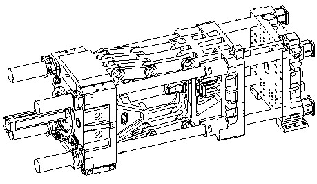
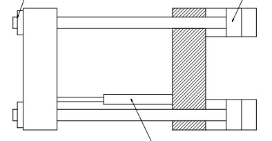
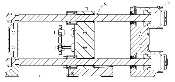
[0037] like Figure 4 As shown, the electric adjustable tie rod type mold clamping mechanism includes ejector mechanism 1, brake mechanism 2, movable platen 3, pull rod 4, fixed platen 5, high pressure mold clamping cylinder 6, quick mold moving cylinder 7, and second plate guide rail 8 , The second plate support slide foot 9, the ejector mechanism 1 is arranged on the movable template 3, the second plate support slide foot 9 is arranged at the bottom of the movable template 3, the second plate support slide foot 9 is placed on the second plate guide rail 8 and guided by it, The quick die-moving oil cylinder 7 moves the movable template 3.

[0038] The brake mechanism 2 is arranged on the movable template 3, and the brake mechanism 2 embraces the pull rod 4 through its brake nut.

[0039] The high-pressure clamping oil cylinder 6 is arranged in the...


PUM


Abstract

The invention discloses an electric pull rod-adjustable mould clamping mechanism. The mechanism comprises an ejection mechanism, a brake mechanism, a moving template, a pull rod, a fixed template, a high-pressure mould clamping cylinder and a quick mould moving cylinder, wherein the ejection mechanism is arranged on the moving template; the quick mould moving cylinder moves the moving template; the brake mechanism is arranged on the moving template; the brake mechanism brakes the pull rod through a brake nut of the brake mechanism; the electric pull rod-adjustable mould clamping mechanism is also provided with an electric pull rod adjusting mechanism which comprises a speed reducer, a servo motor, a speed reducer connection end cover, lead screws of a lead screw pair, screw nuts of the lead screw pair and a pull rod nut, wherein the servo motor is connected with the speed reducer; the speed reducer is fixed on the speed reducer connection end cover; the speed reducer connection end cover is fixed at the front end of the mould clamping cylinder; the front cover of the mould clamping cylinder is fixed on the fixed template; the servo motor is connected with the lead screws of the lead screw pair; and the screw leads of the screw lead pair are matched with the screw nuts of the screw lead pair which is fixed on the head of the pull rod.

Description

technical field [0001] The invention relates to a component of an injection molding machine, in particular to a mold clamping mechanism of an injection molding machine. Background technique [0002] At present, in the domestic injection molding machine industry, the connecting rod type clamping device occupies the main position, and its structure is as follows figure 1 As shown, the defect of its structure is that for a certain tonnage machine, the mold opening stroke is limited by the structure, and the stroke should not be too large. For some products with deep cavity holes, this kind of machine cannot meet the requirements of the product, and the structure of the connecting rod machine is also more complicated. When the tonnage of the machine is relatively large, the length and weight of the machine are relatively large, and the cost will be corresponding improved. [0003] In industrially developed countries such as Germany, the United States, and Japan, most of the la...

Claims


Application Information

Patent Timeline
Patent Type & Authority Applications(China)
IPC IPC(8): B29C45/68
Inventor 阮剑波
Owner HAITIAN PLASTICS MACHINERY GRP
Why Eureka
Try Eureka