
High voltage switch locking device
A high-voltage switch and locking device technology, which is applied to the power device, electric switch, and electrical components inside the switch to achieve the effects of reducing labor intensity, convenient operation, and ensuring reliability
- Summary
- Abstract
- Description
- Claims
- Application Information
AI Technical Summary
Problems solved by technology
Method used
Image

Examples
Embodiment Construction
[0019] The substantive features of the present invention will be further described below in conjunction with the accompanying drawings and specific embodiments.
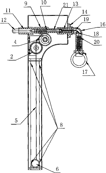
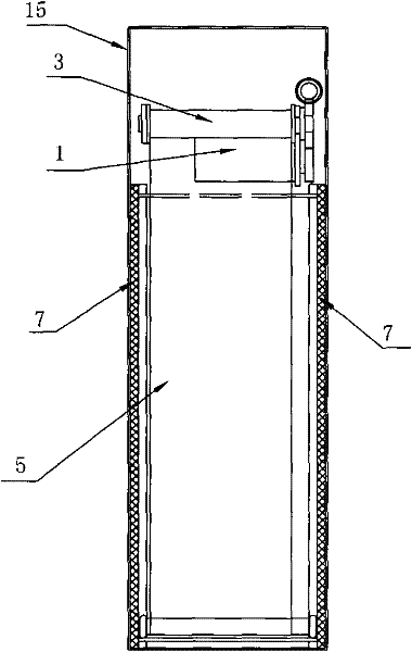
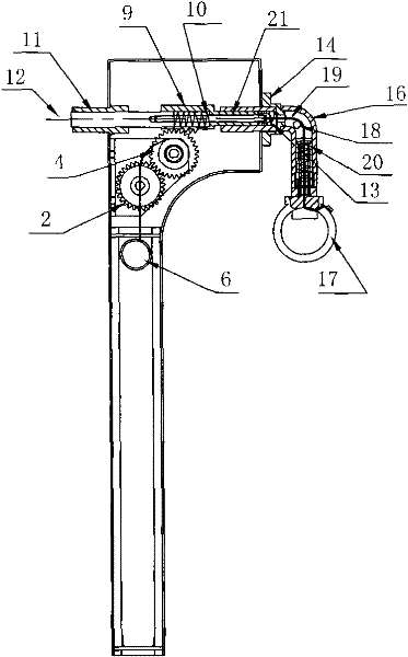
[0020] Such as Figure 1-4 As shown, the high-voltage switch locking device includes a casing 15, and a fixed bushing 11 is embedded in the casing 15, and a locking pin 12 that is movably connected is arranged in the fixed bushing 11, and the rear end of the locking pin 12 is connected to the The movable gear rod 9 driven by the electric drive assembly is connected. The electric drive assembly includes a motor 1, a motor gear 2 installed on the output shaft of the motor, and a shaft gear 4 meshed with the motor gear 2. The upper edge of the shaft gear 4 is located on the stroke of the movable rack 9. The shaft gear 4 is connected with a listing shaft 3 with a warning banner 5 . The lower end of the warning banner 5 is connected with a round steel hanging shaft 6, and the two side walls of the box body 15 along the ...
PUM
 Abstract
Description
Claims
Application Information