Elevator controller and elevator apparatus

A technology of elevator control device and elevator car, which is applied to elevators, transportation and packaging, elevators and other directions in buildings to achieve the effect of alleviating discomfort and simple equipment structure

Inactive Publication Date: 2011-05-18
MITSUBISHI ELECTRIC CORP
View PDF3 Cites 19 Cited by
  • Summary
  • Abstract
  • Description
  • Claims
  • Application Information

AI Technical Summary

Problems solved by technology

[0018] That is, the effect obtained by changing the air pressure in the elevator car at a certain rate of change is relatively small in the elevator of a super high-rise building.

Method used


Image

  • Elevator controller and elevator apparatus
  • Elevator controller and elevator apparatus
  • Elevator controller and elevator apparatus

Examples


Embodiment approach 2

[0133] In Embodiment 2, a mode in which the car room 1 is raised and lowered according to different speed patterns when the car room 1 is raised and when the car room 1 is lowered will be described.

[0134] Hereinafter, matters different from Embodiment 1 will be described, and the contents of matters whose description is omitted are the same as those in Embodiment 1. FIG.

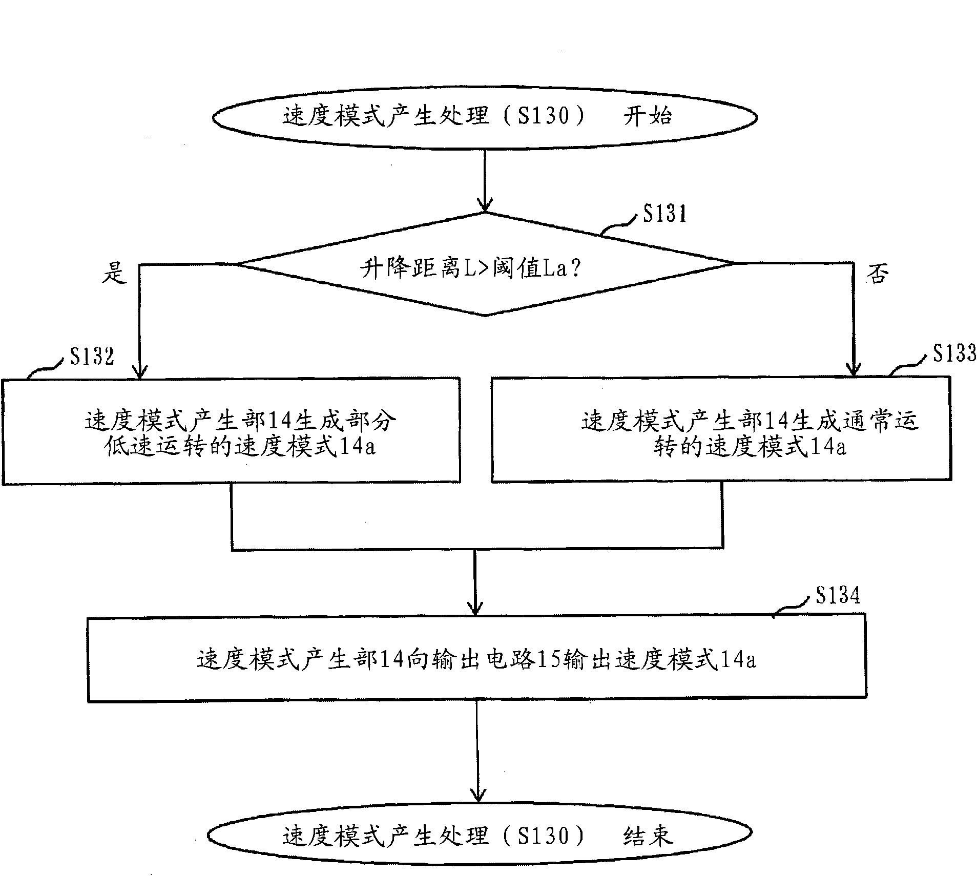
[0135] Figure 7 It is a flowchart of the speed pattern generation process (S130) of Embodiment 2.

[0136] Below, according to Figure 7 The speed pattern generation process (S130) of the second embodiment will be described.

[0137] Here, it is assumed that the ascending and descending distance calculation unit 13 outputs the ascending and descending distance L of the car room 1 to the speed pattern generating unit 14, representing the current position “L” of the car room 1. 1 ” and the stop position of car room 1 at the destination floor “L 2 "The lifting distance information 13a.

[0138]

[01...

Embodiment approach 3

[0152] In the form described in Embodiment 3, an air supply fan is provided in the car room 1, and the air pressure in the car room 1 is adjusted by combining speed control by the speed pattern and pressurization control by the air supply fan.

[0153] Hereinafter, matters different from Embodiment 1 and Embodiment 2 will be mainly described, and the contents of matters whose description is omitted are the same as Embodiment 1 or Embodiment 2. FIG.

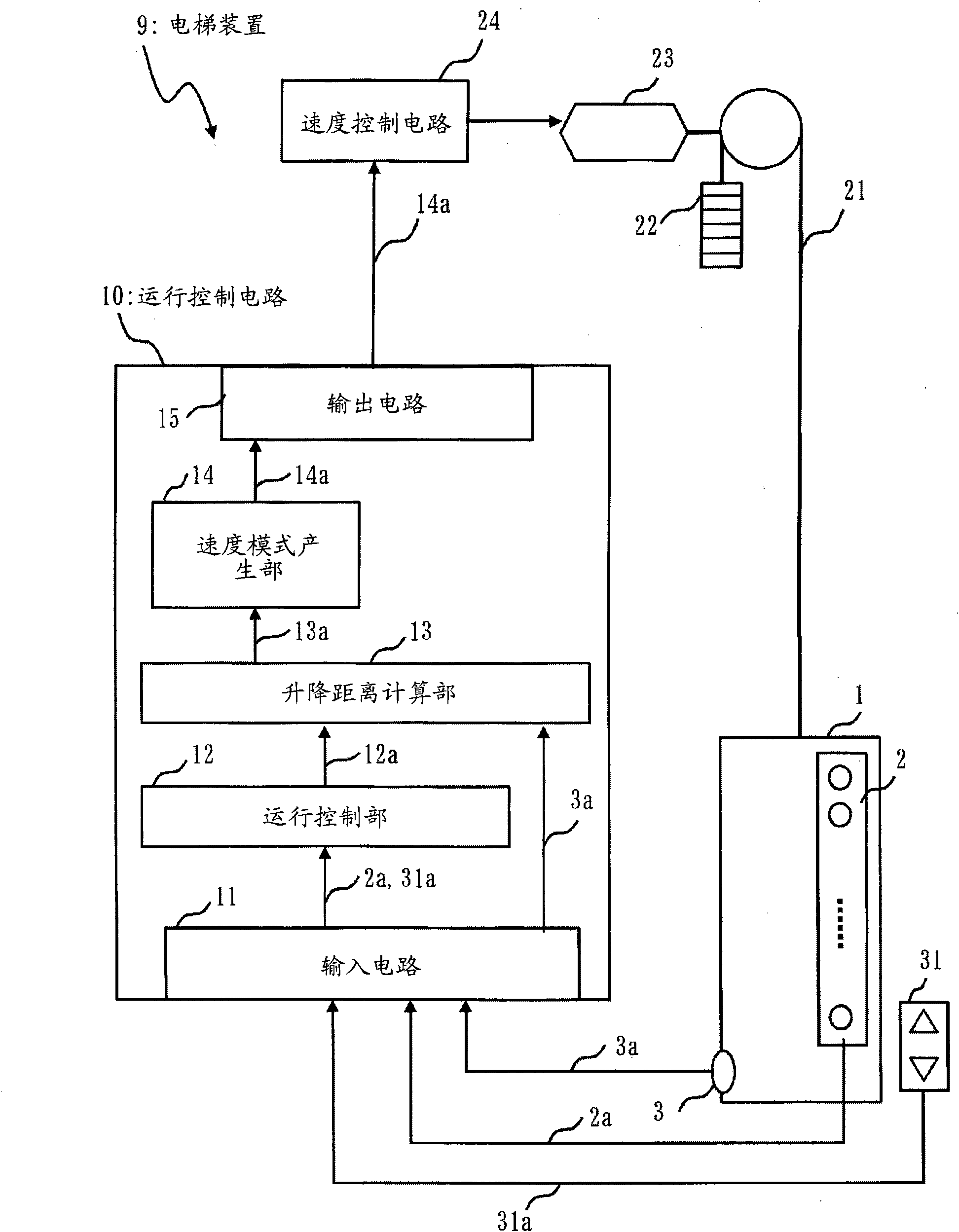
[0154] Figure 8 It is a block diagram of the elevator apparatus 9 of Embodiment 3.

[0155] Below, according to Figure 8 The structure of the elevator apparatus 9 of Embodiment 3 is demonstrated.

[0156] The car room 1 is provided with the following parts as the air pressure control device 7: the air supply fan 5, which pressurizes the car room 1 by supplying air to the car room 1; the air pressure control circuit 4, which controls Air supply fan 5.

[0157] Furthermore, the operation control circuit 10 has an air pressure ...


PUM


Abstract

An elevator controller provided to an elevator capable of lessening the unpleasant feeling of the passenger(s) due to ear popping without lowering the operation efficiency of the elevator more than required. An elevation / descent distance calculating section (13) calculates the elevation / descent distance of the car (1) controlled by the elevator controller from destination floor information (12a) and car position command signal (3a) and outputs elevation / descent distance information (13a) to a speed pattern generating section (14). The speed pattern generating section (14) compares in magnitude the elevation / descent distance and a predetermined distance. If the elevation / descent distance is shorter than the predetermined one, the speed pattern generating section (14) generates a speed pattern (14a) for normal operation; if longer, the speed pattern generating section (14) generates a speed pattern (14a) for partial low-speed operation. The predetermined distance indicates the height difference corresponding to the air pressure difference which brings the passenger(s) opening the Eustachian tube to solve the ear popping. A speed control circuit (24) elevates / descends the car (1) according to the speed pattern (14a). As a result, after the first opening of the Eustachian tube, the car (1) elevates / descends at low speed, the interval until the car (1) elevates / descends a height difference causing the next ear popping can be lengthened, and the unpleasant feeling of the passenger(s) due to the ear popping can be lessened.

Description

technical field [0001] The present invention relates to, for example, an elevator control device and an elevator device for alleviating passengers' discomfort caused by ear pressure. Background technique [0002] There are following technologies: in order to alleviate the discomfort caused by the ear pressure of the passengers during the lifting process of the elevator, the elevator is operated at a low speed (patent document 1, patent document 2), or the rate of change of the air pressure in the elevator car is controlled It is a fixed value technique (Patent Document 3). [0003] Figure 19 It is a figure which shows the speed control mode of the conventional elevator. [0004] exist Figure 19 Among them, according to Patent Document 1 and Patent Document 2, the elevator car travels from the departure floor to the destination floor at a rate higher than the rated speed ( Figure 19 The solid line shown a 1 ) slow low speed ( Figure 19 The dotted line shown a 2 ) march...

Claims


Application Information

Patent Timeline
Patent Type & Authority Applications(China)
IPC IPC(8): B66B1/30
CPCB66B11/024B66B1/285B66B1/30
Inventor 山本圭悟
Owner MITSUBISHI ELECTRIC CORP
Why Eureka
Try Eureka