Method for manufacturing warp and conical warping device

A warping and warp technology, applied in the field of warp manufacturing, can solve problems such as damage to the pressing roller, damage to the handle, and inability to achieve, and achieve the effect of improving uniformity

Active Publication Date: 2011-08-03
KARL MAYER STOLL R&D GMBH
View PDF4 Cites 3 Cited by
  • Summary
  • Abstract
  • Description
  • Claims
  • Application Information

AI Technical Summary

Problems solved by technology

However, until now this has not been possible with dispensing devices with a handle, because the pressure rollers collide with the handle of the dispensing device
This can result in damage to the rollers or damage to the handle

Method used


Image

  • Method for manufacturing warp and conical warping device
  • Method for manufacturing warp and conical warping device
  • Method for manufacturing warp and conical warping device

Examples


Embodiment Construction

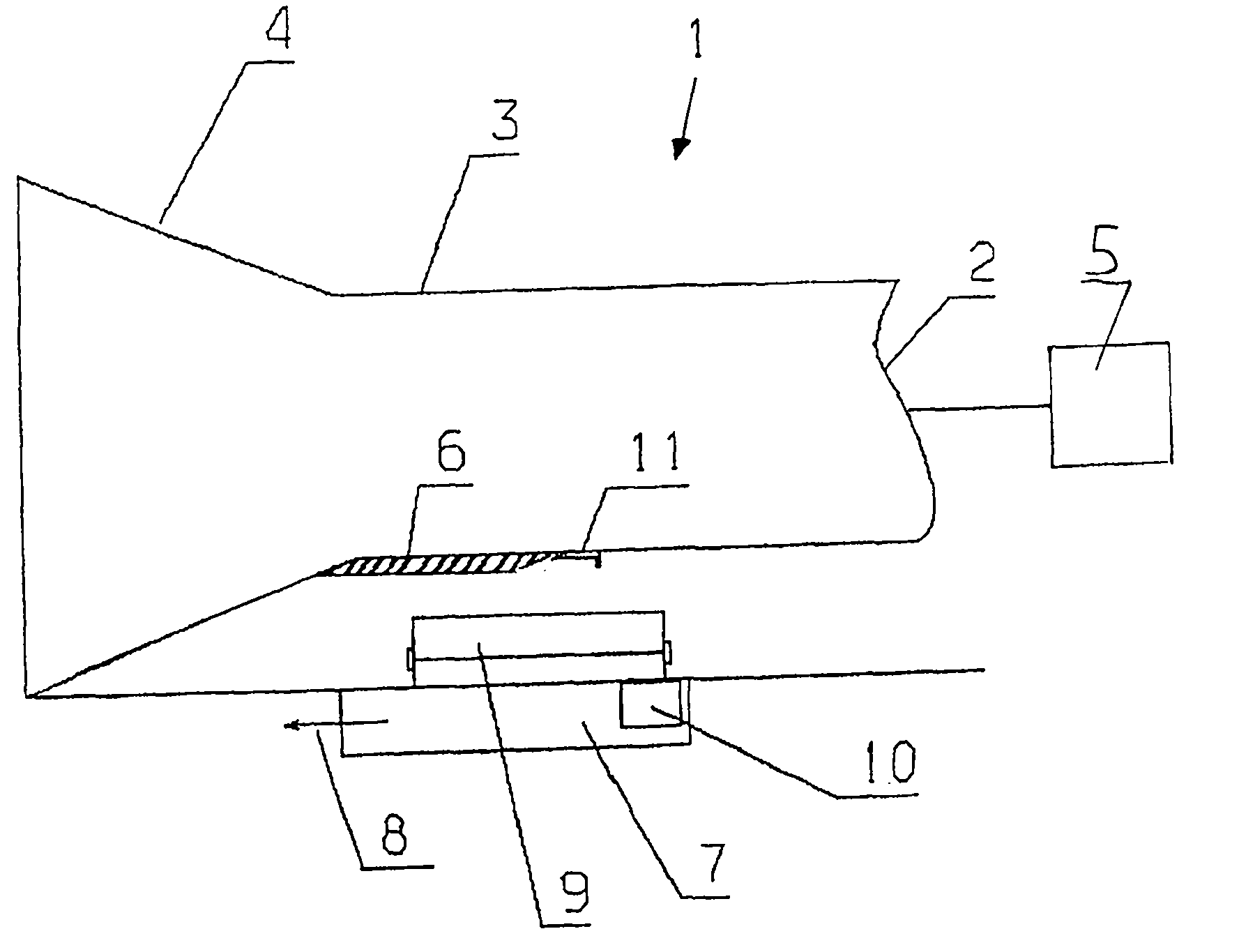
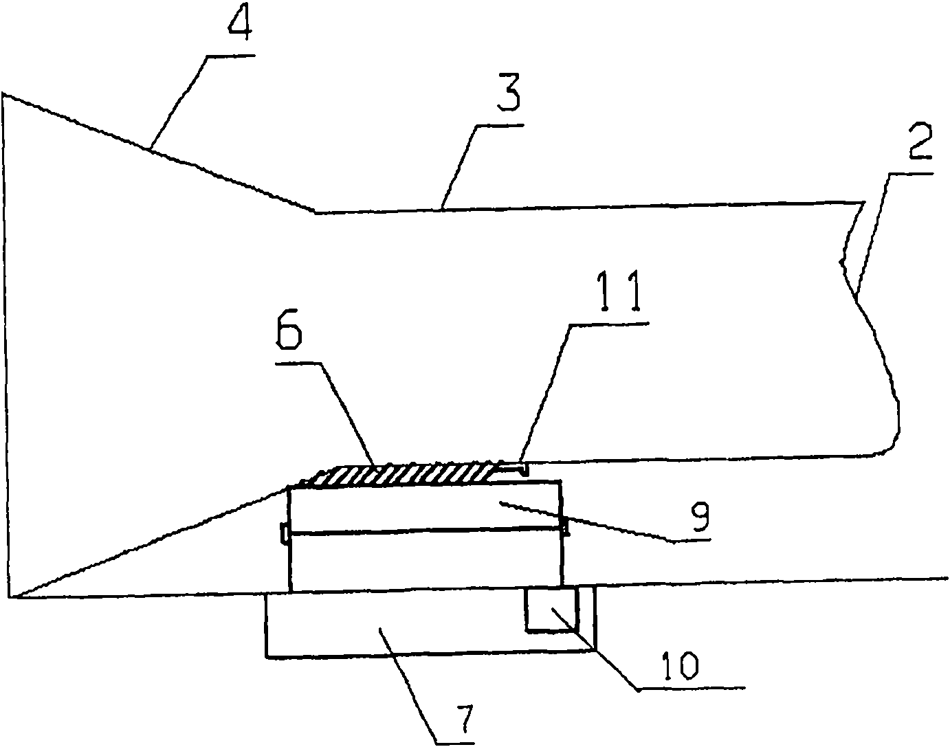
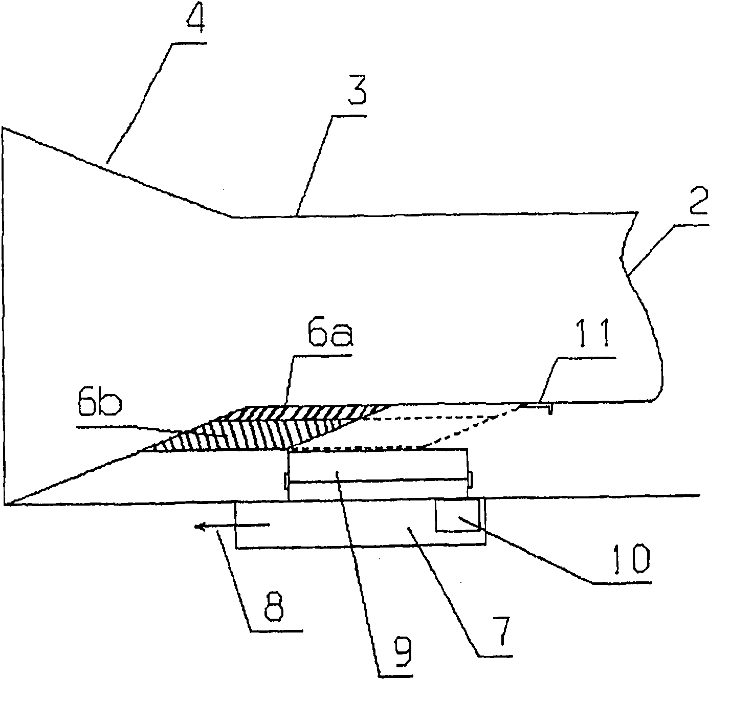
[0026] The conical warping machine 1 has a warping cylinder 2 with a cylindrical section 3 and a conical section 4 . The warping cylinders are rotated by a drive 5 which is only schematically shown.

[0027] A plurality of yarns are drawn parallel to one another from a creel, not shown in detail, in which a coil is arranged for each yarn. Sheets of yarns made up of yarns parallel to each other are also referred to as "stripes". When the warping cylinder 2 turns, such strips are drawn onto the circumference of the warping cylinder 2 and form the yarn reel 6 there.

[0028] For the sake of clarity, the reel 6 is shown here only on the lower edge of the warping cylinder 2 . Of course, the yarn reel 6 surrounds the warping cylinder 2 .

[0029] The lower layer of the strip is placed on the cylindrical section 3 . All other layers of the strip then move a short distance in the offset direction, that is, parallel to the axis of the warping cylinder 2 (to the left in the present ...


PUM


Abstract

The invention relates to a method for manufacturing warps and a conical warping device. According to the method, a warping roller (2) is rotated and at least one belt formed from yarn sheets is winded on the warping roller (2) so as to form a yarn roll (6), wherein at least one internal distributing device is used which is provided with a handle (11) at an end part protruding out of the yarn roll (6), and the handle has a predetermined radially-extending part. The purpose is to expand the possibility for influencing the yarn roll structure. Thus it is specified that when the yarn roll (6) reaches a radial thickness which at least corresponds to the radially-extending part of the handle (11), a pressure roller (9) is leaned against the yarn roll (6).

Description

technical field [0001] The invention relates to a method for producing warp threads, in which method a warping cylinder is rotated and at least one strip of yarn sheets is simultaneously wound onto the warping cylinder and thus a roll is produced, wherein at least one Internal dispensing device, which is provided with a handle on the end protruding outward from the yarn roll, said handle has a predetermined radial extension. [0002] Furthermore, the invention relates to a conical warping device with a warping cylinder and at least one inner distribution device with a handle having a radial extension towards the warping cylinder. Background technique [0003] Warp threads usually have a large number of threads arranged in parallel, so that it is not possible to draw all the threads out of the creel at the same time. For this reason, usually a plurality of yarns are bundled into a so-called "band" and the band is wound around the circumference of the warping cylinder by rota...

Claims


Application Information

Patent Timeline
Patent Type & Authority Applications(China)
IPC IPC(8): D02H13/00D02H3/00
CPCD02H3/00D02H9/00D02H3/02
Inventor M·富尔R·科恩
Owner KARL MAYER STOLL R&D GMBH
Why Eureka
Try Eureka