Device for putting weft thread band

A yarn piece and weft laying technology, which is applied to textiles and papermaking, flat warp knitting machines, knitting, etc., can solve the problems of complex structure of known devices, and achieve the effects of simplifying yarn threading and increasing operating speed

Active Publication Date: 2011-08-03
KARL MAYER CHINA
View PDF8 Cites 5 Cited by
  • Summary
  • Abstract
  • Description
  • Claims
  • Application Information

AI Technical Summary

Problems solved by technology

This on the one hand makes the structure of the known device relatively complex and on the other hand the move

Method used


Image

  • Device for putting weft thread band
  • Device for putting weft thread band
  • Device for putting weft thread band

Examples


Embodiment Construction

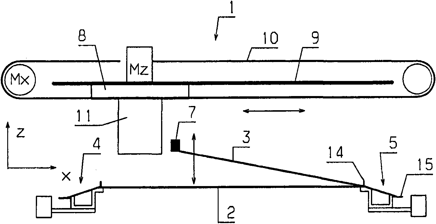
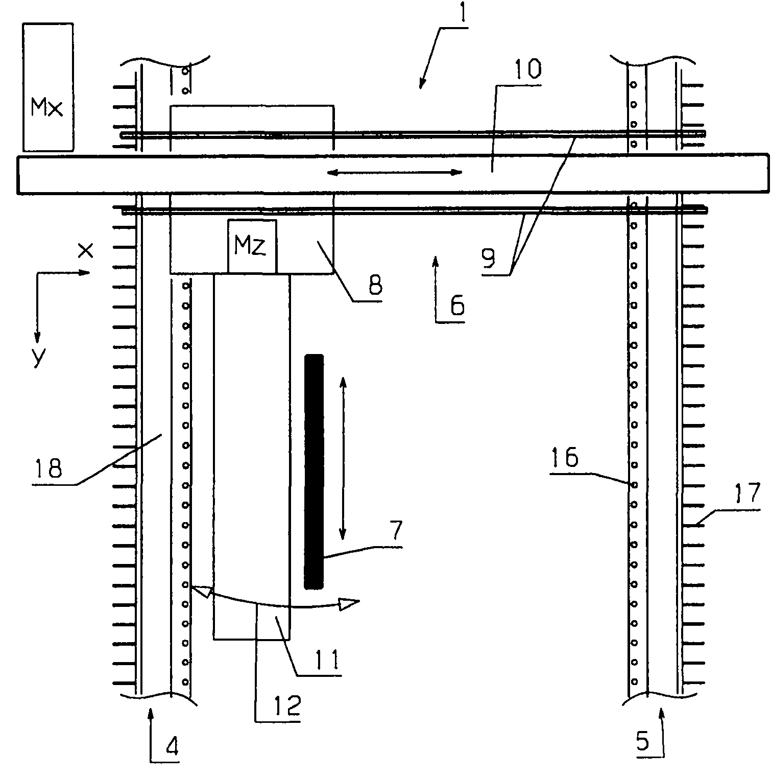
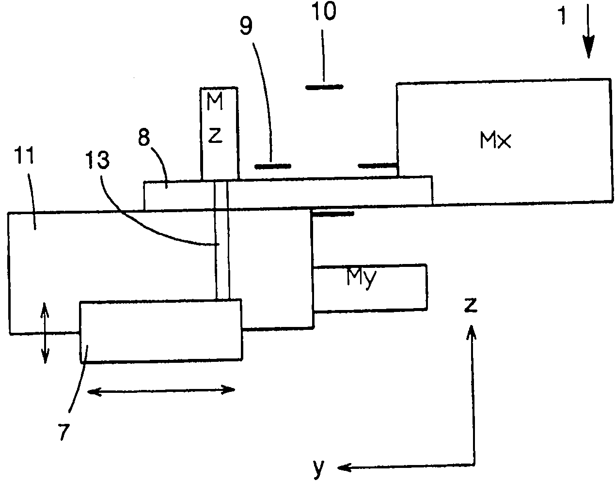
[0022] figure 1 A device 1 for laying weft thread sheets 2 , 3 is shown schematically. The weft thread sheet 2 has been laid between two sheet conveying devices 4 , 5 and is conveyed by the sheet conveying devices 4 , 5 in a conveying direction 6 of a reinforcing device, not shown in detail, eg a knitting device. Conveying direction 6 in figure 1 perpendicular to the plane of the drawing.

[0023] To simplify the description below, the three directions are labeled x, y and z below. The first direction x runs between the two sheet transport devices 4 , 5 . However, this direction does not have to be perpendicular to the conveying direction 6 . The angle between the first direction x and the conveying direction 6 can also be different from 90°. The terms "first", "second" and "third" do not imply that the movements must be performed in the corresponding order.

[0024] The second direction y extends perpendicularly to the first direction x and thus parallel to the conveyin...


PUM


Abstract

The invention discloses a device (1) for putting weft thread bands, which comprises a carriage (8) which is movable in a primary direction and supports a thread lever (7) that is movable in a secondary direction (y) and a third direction (z) opposite the carriage (8). A direction component of the secondary direction (y) runs perpendicular to the primary direction. The third direction comprises a direction component that is perpendicular to the primary direction and perpendicular to the secondary direction (y). The movement of the thread lever (7) is expected to be controlled with precision as high as possible. Therefore, a motor (Mz) movable by the carriage (8) is provided, which drives the thread lever (7) in the third direction (z).

Description

technical field [0001] The invention relates to a device for laying a sheet of weft yarn, having a spinning wheel movable in a first direction and supporting a laying device movable in a second direction and relative to the spinning wheel A third direction moves, wherein the second direction has a directional component perpendicular to the first direction, and the third direction has a directional component perpendicular to the first direction and perpendicular to the second direction. Background technique [0002] Such a device is known, for example, from DE 197 42 721 C1. The yarn laying device can move on the motion track of the three-dimensional structure. The layer lays each yarn sheet between two conveyor chains or other conveyor devices. To this end, the yarn lapper is moved from the first conveying device to the second conveying device. This direction is called "first direction". Before the yarn layer moves back to the first conveyor, it moves along the direction...

Claims


Application Information

Patent Timeline
IPC IPC(8): D04B27/10D04B23/12
CPCD04B23/12
Inventor S・佩特伦茨J・尼斯特勒S・尤利格
Owner KARL MAYER CHINA
Why Eureka
Try Eureka