Ratchet spanner

A ratchet wrench and ratchet technology, applied in the field of wrenches, can solve problems such as high product defects, damage, and poor product evaluation

Inactive Publication Date: 2011-08-10
胡厚飞
View PDF1 Cites 3 Cited by
  • Summary
  • Abstract
  • Description
  • Claims
  • Application Information

AI Technical Summary

Problems solved by technology

[0005] However, after repeated switching actions, the two parallel sides of the groove and the outer periphery of the protrusion will produce a lot of iron filings due to reciprocating friction, and these iron filings are easily stuck on the two parallel sides of the groove and the outer periphery of the protrusion. between, forming an obstacle to the switching action
This kind of unsmooth switching usually deeply affects the

Method used


Image

  • Ratchet spanner
  • Ratchet spanner
  • Ratchet spanner

Examples


Embodiment Construction

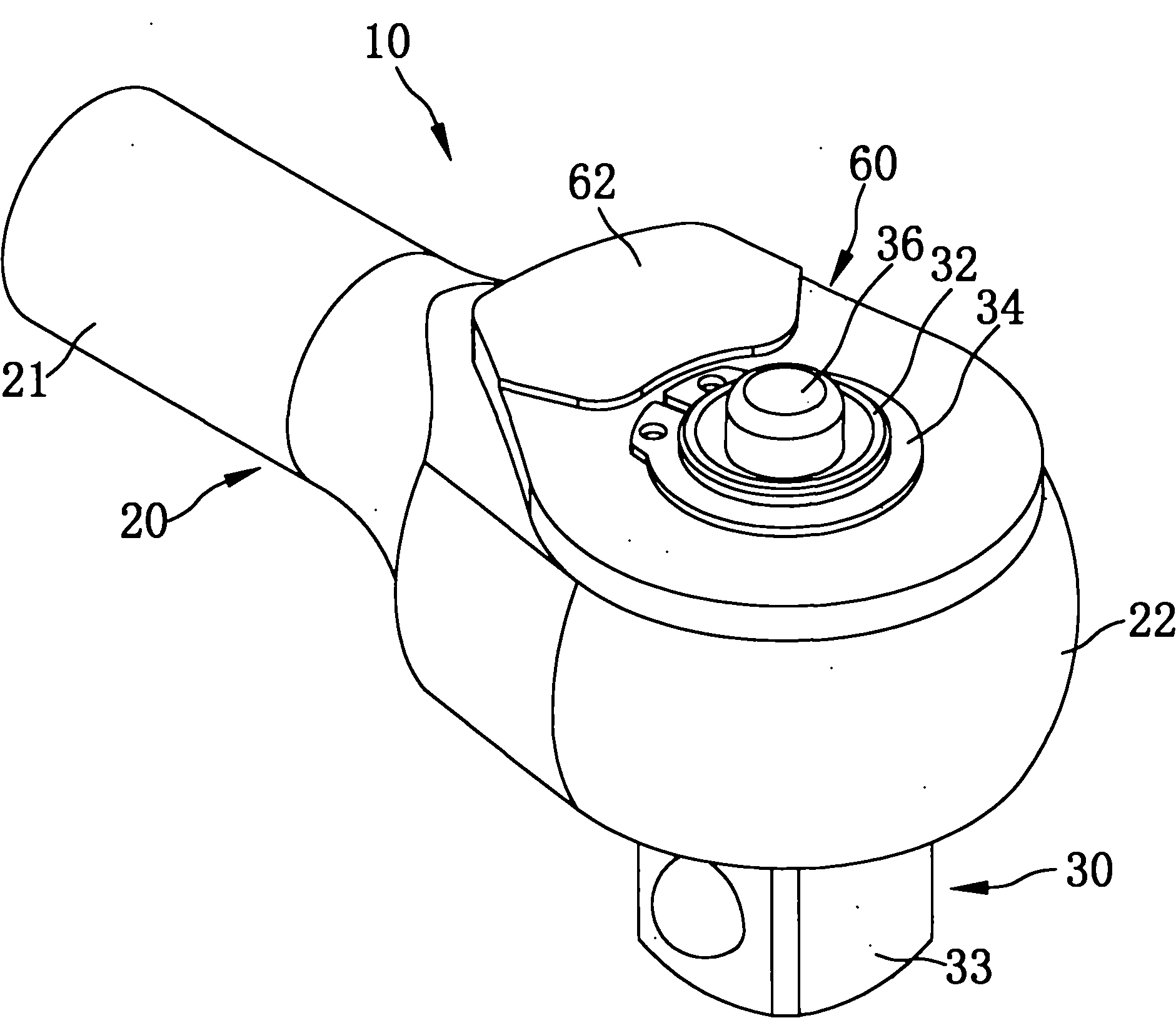
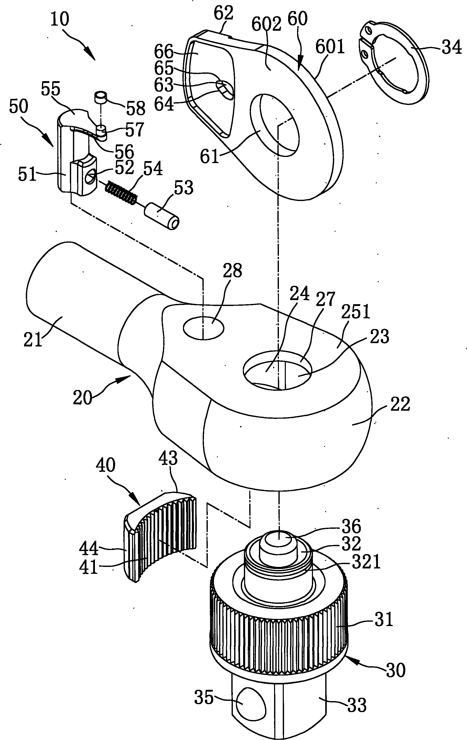
[0034] refer to Figure 1 to Figure 6, is the first embodiment of the ratchet wrench of the present invention. The ratchet wrench 10 of the present invention includes a body 20, a driving body 30, a ratchet block 40, a reversing switch 50 and a control member 60; wherein:

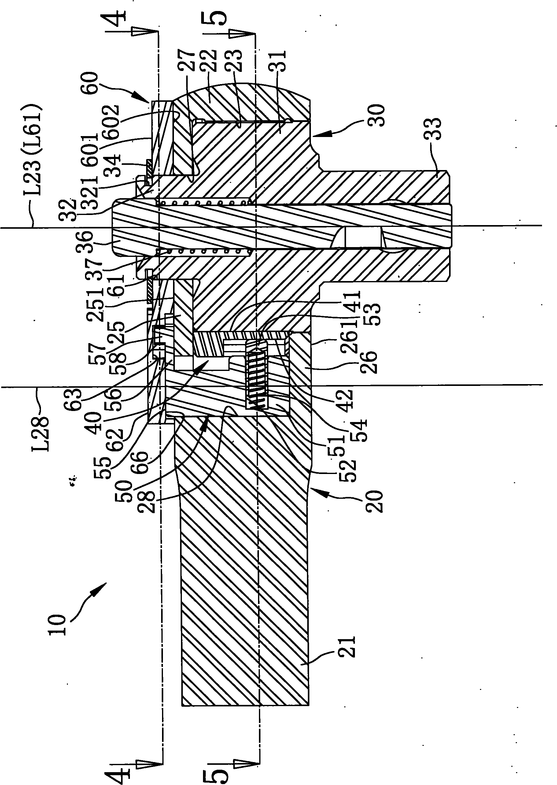
[0035] The body 20 has a handle 21 and a head 22 disposed at one end of the handle 21. A circular first receiving groove 23 is provided in the head 22. The first receiving groove 23 has an axis L23, and the user The main body 20 can be rotated around the axis L23 of the first accommodating groove 23 by operating the handle 21 .

[0036] The head 22 is provided with a first stop wall 25 and a second stop wall 26 opposite to each other, and the head 22 is formed with a first surface 251 on the outer surface of the first stop wall 25, and the head 22 is formed on the second stop wall 26. A second surface 261 is formed on the outer surface of the first accommodating groove 23 .

[0037] The first stop wall 2...


PUM


Abstract

The invention relates to a ratchet spanner for ensuring switching of a control part smoother, which adopts the following technical scheme that a first edge of a control slot is contacted with the outer periphery of a guide part of a reversing switch; and an included angle between a tangent line formed when the first edge is tangential to the guide part and a second reference line of the reversing switch is not more than 45 degrees. Therefore, if a user wants to shift the control part to a second position from a first position, most of the shifting force applied by the user to the control part can be used for pushing the guide part of the reversing switch and ensuring the reversing switch to rotate relative to a pivot slot and cannot cause the problem that the control part and the reversing switch are clamped or are not shifted to rotate smoothly. Therefore, the user can easily shift a shifting part of the control part so that the control slot drives the reversing switch to move.

Description

technical field [0001] The invention relates to a wrench, in particular to a ratchet wrench with automatic positioning and a control member that can be easily turned by a user. Background technique [0002] Please refer to US Patent No. 7,278,339 "Reversible ratchet wrench", which is a reversible ratchet wrench. This ratchet wrench uses a ring to drive a switching member to produce position changes in two directions, and the front end of the switching member is equipped with a pressing member and an elastic element to elastically push the trigger A pawl that allows the pawl to be controlled to move between two positions and engages a drive member. [0003] Firstly, it can be noticed that the reversing ratchet wrench is pivoted on the rotating assembly by a reversing plate and can be operated by the user, and then the ring is driven to perform the reversing action. An elongated groove (slot) is provided in the tip piece (tip piece) formed at one end of the ring, and the tra...

Claims


Application Information

Patent Timeline
IPC IPC(8): B25B13/46
Inventor 胡厚飞
Owner 胡厚飞
Why Eureka
Try Eureka