
Device capable of increasing flame height

A technology of flame height and gas passage, which is applied to gas fuel burners, combustion methods, combustion types, etc., and can solve problems such as flame height and shape difficulties

Active Publication Date: 2014-09-10
PRO IRODA INDS
View PDF6 Cites 1 Cited by
  • Summary
  • Abstract
  • Description
  • Claims
  • Application Information

AI Technical Summary

Problems solved by technology

However, the air inlet designed in this way is located on the plane and above the combustion port, and the air inlet direction is perpendicular to the flame burning direction, which can only provide continuous combustion of the flame, and it is difficult to maintain a stable flame height and shape.

Method used


Image

  • Device capable of increasing flame height
  • Device capable of increasing flame height
  • Device capable of increasing flame height

Examples


Embodiment Construction

[0039] Regarding the technology, means and effects adopted by the present invention, two preferred embodiments are given and described in detail below with accompanying drawings, which are for illustration only and are not limited by this structure in patent applications.

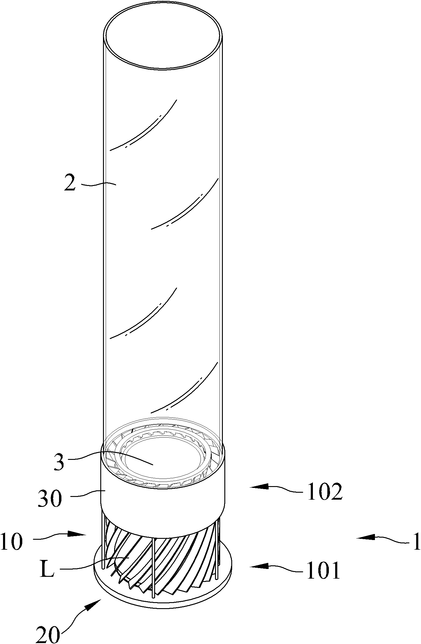
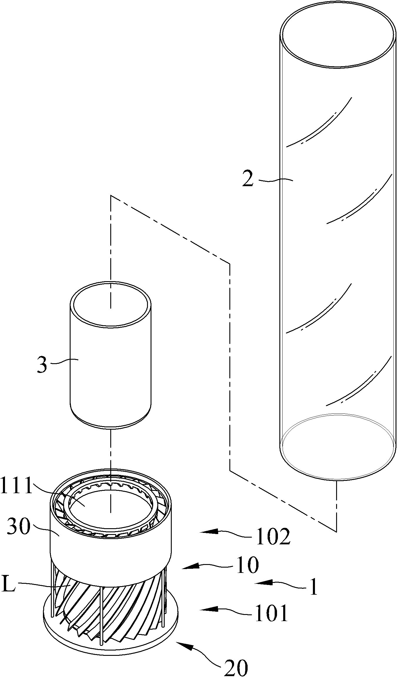
[0040] refer to figure 1 and figure 2 , is the three-dimensional appearance view and three-dimensional exploded view of the first embodiment of the device for increasing the flame height of the present invention. The device that can increase the flame height of the present invention includes an air intake group 1 and a transparent cover 2, the air intake group 1 is provided with an inner wall 111, the inner wall 111 is closed, and the air intake group 1 is further provided with several There are 11 to 23 spiral air channels L in this embodiment, which can provide a stable flame. The two ends of the intake group 1 respectively form an intake area 101 and an acceleration area 102, the spiral air channel L ...


PUM


Abstract

The invention relates to a device capable of increasing flame height, which comprises an air intake group and a light transmitting cover, wherein the air intake group is provided with an inner wall, and the inner wall is closed; the air intake group is circlewise provided with a plurality of swirling air channels, and two ends of the air intake group are respectively provided with an air intake area and an accelerating area; the swirling air channels are communicated with the air intake area and the accelerating area, and the air intake area and the accelerating area are adjacent; the air intake area causes the swirling air channels to be open, and the accelerating area causes the swirling air channels to be closed; and the light transmitting cover is connected with the accelerating area. External air enters the swirling air channels of the accelerating area from the swirling air channels of the air intake area, and the air rotates through the swirling air channels and drives flame to rotate. When the air passes through the accelerating area, the flow of air can be accelerated, and the air quickly forms cyclone in the light transmitting cover to increase the flame height.

Description

technical field [0001] The invention mainly discloses a device capable of increasing flame height. Background technique [0002] Referring to U.S. Patent No. 7097448 "VORTEX TYPE GAS LAMP", it discloses that a vortex type gas lamp 10 can be used to make combustible gas generate an upward vortex flame, and the vortex flame is located in a surrounding area and a Within the boundary of the vortex air, there will be an interface located in the central area of ​​the vortex air and gas during operation. There is no gas in the vortex air, and the combustion of gas is limited by this interface. The gas lamp 10 has a central axis 18 , the gas lamp 10 includes: a base 11 with a surface extending laterally along the central axis 18, airless combustible gas can be provided by the base 11 and adjacent to the central axis 18; a shield 20 includes a first and a second Two axially extending blocks 21; 22, each block 21; 22 have an upper end and a lower end, the lower end of each block 21; ...

Claims


Application Information

Patent Timeline
Patent Type & Authority Patents(China)
IPC IPC(8): F23D14/84
Inventor 陈维隆陈建男
Owner PRO IRODA INDS
Learn More