Correction clamp for machining center

A machining center and fixture technology, which is applied in the direction of manufacturing tools, metal processing equipment, metal processing machinery parts, etc., can solve the problems of calibration reference range limitation, difficulty in accurate alignment of large-diameter reference holes, waste of time, etc.

Inactive Publication Date: 2012-09-26
苏州市新鸿基精密部品有限公司
View PDF7 Cites 5 Cited by
  • Summary
  • Abstract
  • Description
  • Claims
  • Application Information

AI Technical Summary

Problems solved by technology

[0002] At present, when the benchmark is aligned during the NC machining and debugging process, the common practice is to directly purchase the dial indicator on the market and install it on the machine for calibration. Ordinary lever gauge calibration is too time-consuming and the calibration range is limited, especially for large-diameter reference holes. Difficult and easy to damage the dial indicator

Method used


Image

  • Correction clamp for machining center
  • Correction clamp for machining center

Examples


Embodiment Construction

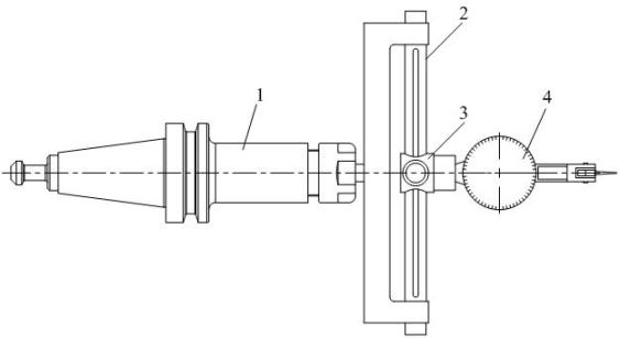
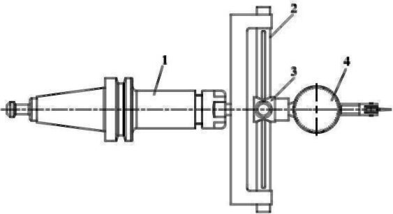
[0011] Such as figure 1 As shown, the machining center calibration fixture includes shaft 1, radial support 2 and moving slider 3. The radial support 2 is fixed on the end of the shaft 1. The locking mechanism is embedded in the chute, and the dial gauge 4 is installed on the moving slider.

[0012] In specific applications, the shaft of the calibration jig is installed on the tool handle, which can quickly align the center of the hole with high efficiency. A set of calibration jigs can be suitable for multi-standard ranges, and the stroke range of benchmark calibration is wide; the cost is low, and the use convenient. Any CNC machining center can be paired with this fixture and gauge.

[0013] It should be understood that: the above is only a preferred embodiment of the present invention, for those of ordinary skill in the art, without departing from the principle of the present invention, some improvements and modifications can also be made, these improvements and Retouch...


PUM


Abstract

The invention provides a correction clamp for a machining center. The correction clamp comprises a shaft, a radial bracket and a movable slide block; the radial bracket is fixed at an end part of the shaft; the movable slide block is mounted on the radial bracket through a locking mechanism; and a dial indicator is mounted on the movable slide block. When the correction clamp is mounted on a knife handle, the center of a hole can be aligned quickly, and the efficiency is high; one set of correction clamp can be suitable for measuring ranges of various specifications, and the travel range of datum correction is wide; and the cost is low and the use is convenient.

Description

technical field [0001] The invention relates to a machining center correction jig, which belongs to the technical field of precision machining equipment. Background technique [0002] At present, when the benchmark is aligned during the NC machining and debugging process, the common practice is to directly purchase the dial indicator on the market and install it on the machine for calibration. Ordinary lever gauge calibration is too time-consuming and the calibration range is limited, especially for large-diameter reference holes. Difficult and easy to damage the dial indicator. Contents of the invention [0003] The purpose of the present invention is to overcome the deficiencies in the prior art, and provide a machining center calibration jig. [0004] The purpose of the present invention is achieved through the following technical solutions: [0005] The machining center correction fixture is characterized by: including shaft, radial bracket and moving slider. surfac...

Claims


Application Information

Patent Timeline
Patent Type & Authority Applications(China)
IPC IPC(8): B23Q17/22
Inventor 李坚
Owner 苏州市新鸿基精密部品有限公司
Why Eureka
Try Eureka