LED illumination light source

A technology of LED lighting and light source, applied in the direction of light source, electric light source, lighting device, etc., can solve the problems of LED floodlight glare, LED floodlight projection, interference with the driver's sight, etc., and achieve adjustable spot size and uniform illumination. , the effect of clear spot

Inactive Publication Date: 2012-09-26
李姝江
View PDF5 Cites 8 Cited by
  • Summary
  • Abstract
  • Description
  • Claims
  • Application Information

AI Technical Summary

Problems solved by technology

To sum up, there are two light sources with different installation methods used for road monitoring lighting: one is a xenon flash, which is a low-power pulsed light source with a small flash index and cannot be installed far away from the illuminated object. Usually installed at a position 10-15 meters in front of the camera can meet the brightness requirements of the camera’s lighting source, and can only shoot vehicles that are close to the flash, or take partial photos of the vehicle, which cannot fully reflect the overall picture of the illegal vehicle. Open the distance from the camera, its small flash index can not meet the lighting needs of shooting; the other is LED floodlights, this kind of lamps are originally used for building floodlighting, its power can do Larger, can be installed in the same position as the camera
However, there are some difficulties and problems when it is used for road monitoring lighting, mainly in the glare of LED floodlights. In some lanes, it will seriously affect and interfere with the driver's sight, which is not conducive to safe driving. The second is the object captured by the camera. At tens of meters away, the light of the LED floodlight cannot be accurately projected onto the shooting target of the camera, resulting in blurred images and failing to achieve the expected shooting effect
If it is installed in a short distance and is restricted by factors such as road, environment, geographical location, engineering installation cost and vehicle driving, this method will not be adopted

Method used


Image

  • LED illumination light source
  • LED illumination light source

Examples


Embodiment Construction

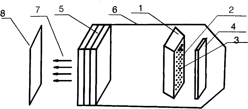
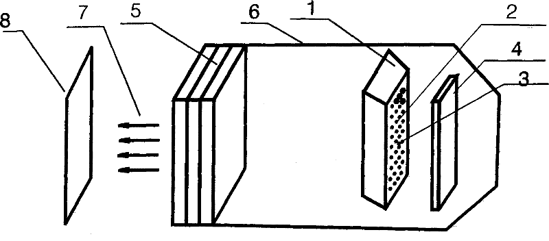
[0011] The present invention is composed of LED light-emitting array 2, color temperature compensation unit 3, optical homogeneous mirror 4, light converging device 5, light converging cover 6, converging light 7, target light spot 8, light converging device (referring to: convex lens, concave lens , Fresnel lens, optical plane mirror and other monomers or combined optical systems) and optical reflector 7, using LED light emitting array 1, color temperature compensation unit 2, as a front-illuminated or rear-illuminated light source, placed At the focal point of the optical light concentrator, the light passing through the optical light concentrator is directed forward, and the light becomes a rectangular beam after passing through the optical light concentrator, and then the optical light concentrator (referring to: convex lens, concave lens, Fresnel lens, etc. body or a combination of optical systems) to project the converged rectangular beam onto the position or object to be...


PUM


Abstract

The invention relates to an LED illumination light source comprising a LED light-emitting array, a colour temperature compensator, an optical light-equalizing mirror, a light gathering device, a light gathering cover, a light after gathering and a target light spot. The LED illumination light source is an LED novel light source that allows colour temperature to be adjustable and can be organically combined with the light gathering device. The a light beam that has been optically processed forms a uniform and clear rectangular light spot with a fixed size at a predetermined target place in front of the light gathering device. The size, the light uniformity and the sharpness of the rectangular light spot can be adjusted through adjusting a focal length among the light gathering device, the optical light-equalizing mirror and the LED light-emitting array.

Description

technical field [0001] The present invention relates to an LED lighting technology, in particular to a lighting system used for flood lighting of vehicles, buildings, stages, squares, roads, and high-beam fields, and for light compensation of photographed positions or objects when taking pictures. LED lighting source. Background technique [0002] Let’s take the application of road vehicle monitoring and lighting as an example. It currently belongs to a brand-new application field of LED light source lighting. The growth of roads has caused road congestion, coupled with individual vehicles that operate out of order and do not obey road traffic rules, which has increased the burden on the overwhelmed roads and brought new issues to road traffic management. It is against this background that road vehicle monitoring is attempted. Road vehicle monitoring mainly adopts camera photography and video recording methods. For vehicles that do not follow traffic rules and violate regu...

Claims


Application Information

Patent Timeline
Patent Type & Authority Applications(China)
IPC IPC(8): F21S2/00F21V13/00F21Y101/02F21K9/69F21Y115/10
Inventor 李姝江
Owner 李姝江
Why Eureka
Try Eureka