Optical component and optical system

A technology of optical components and components, applied in the field of optical systems, can solve the problems such as the reduction of visual recognition of aerial images

Inactive Publication Date: 2013-01-09
SHARP KK
View PDF17 Cites 2 Cited by
  • Summary
  • Abstract
  • Description
  • Claims
  • Application Information

AI Technical Summary

Problems solved by technology

Stray light mixed with light that aids imagin...

Method used


Image

  • Optical component and optical system
  • Optical component and optical system
  • Optical component and optical system

Examples


Embodiment Construction

[0068] Hereinafter, embodiments of the present invention will be described with reference to the drawings. The invention is not limited to the embodiments shown by way of example.

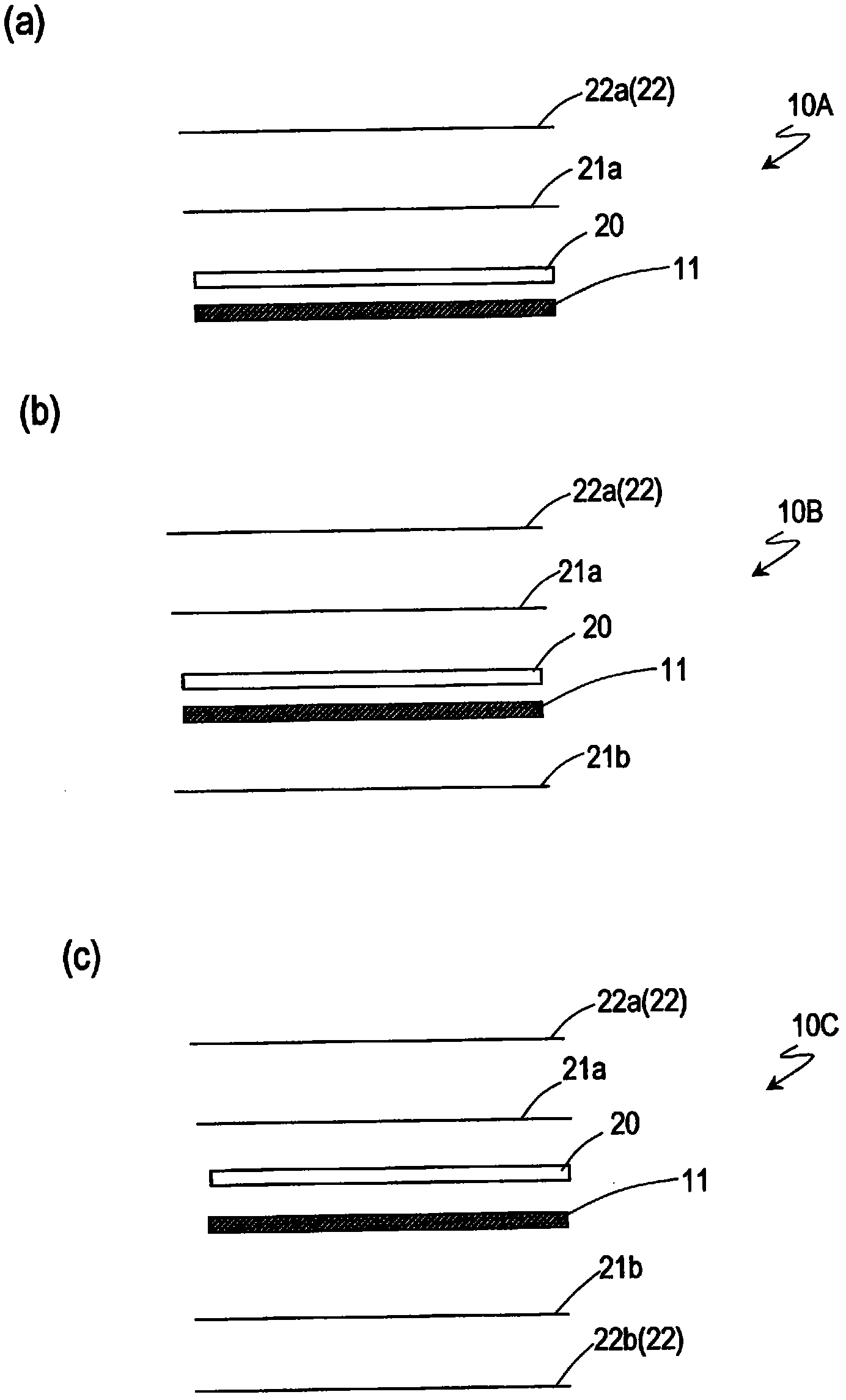
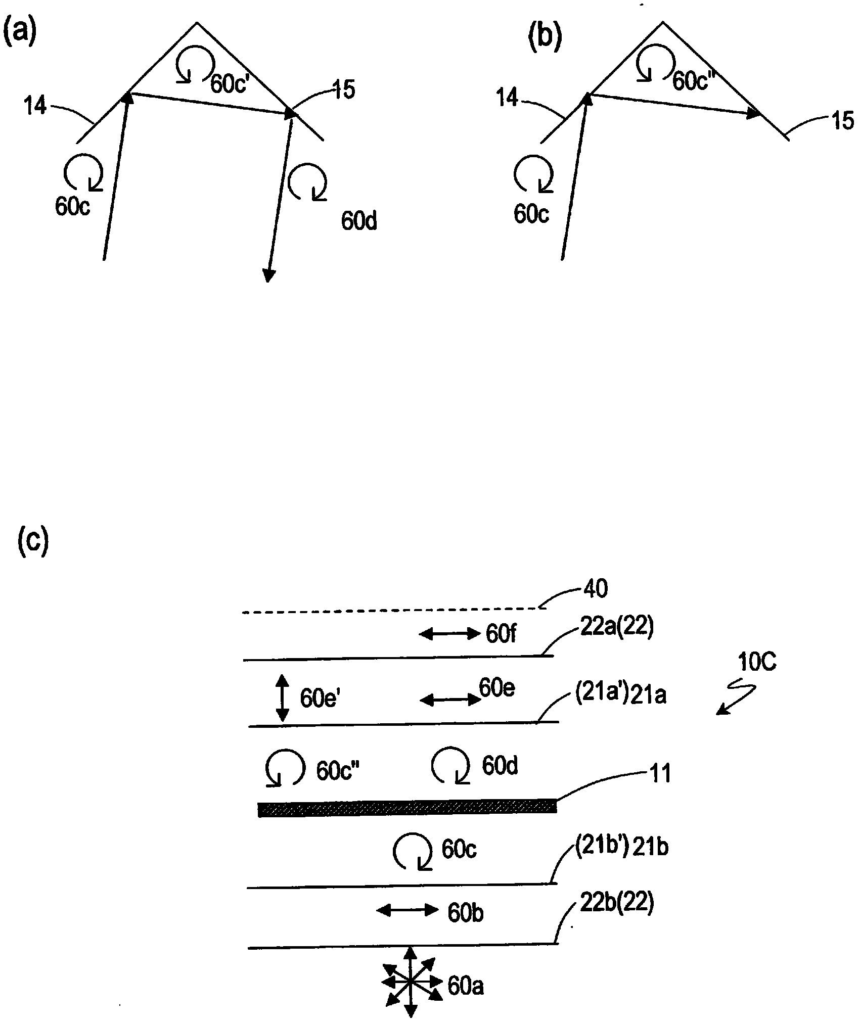
[0069] refer to figure 1 (a)~ figure 1 (c) The configuration of the optical elements 10A, 10B, and 10C according to the embodiment of the present invention will be described. figure 1 (a)~ figure 1 (c) is a schematic cross-sectional view showing the configuration of the optical elements 10A, 10B, and 10C. In addition, the same reference numerals are assigned to common components to avoid duplication of description.

[0070] figure 1 The optical element 10A shown in (a) has: a reflective imaging element 11; a first polarizing plate 22a disposed on the light-emitting side of the reflective imaging element 11; and disposed between the reflective imaging element 11 and the first polarizing plate 22a. the first retardation plate 21a; and, for example, the transparent substrate 20 disposed bet...


PUM


Abstract

Disclosed is an optical component (10A) which includes a reflection imaging element (11) for reflecting a beam of light from a projected object an even number of times to image the projected object; a first polarizing plate (22) disposed on the light transmitting side of the reflection imaging element (11); and a first phase difference plate (21a) interposed between the reflection imaging element (11) and the first polarizing plate (22).

Description

technical field [0001] The present invention relates to an optical system including a reflective imaging element capable of forming an image of a projected object in space and a display panel. Background technique [0002] Recently, optical systems for spatially imaging an object to be projected using reflective imaging elements have been proposed (for example, Patent Documents 1 to 6). The optical system has a reflective imaging element and a projected object, and the image displayed in space (called an aerial image) is obtained by imaging the image of the projected object at a symmetrical position with the reflective imaging element as the plane of symmetry. [0003] In the reflective imaging element disclosed in Patent Document 1, a plurality of through holes penetrating the thickness direction of the flat substrate are provided, and an optical element including two mirror elements perpendicular to the inner walls of each hole is formed (refer to Patent Document 1 of Fi...

Claims


Application Information

Patent Timeline
IPC IPC(8): G02B5/00G02B5/30G02F1/13363G02B1/11G02B1/118G02B5/08G02B30/25
CPCG01C11/00G02B27/286G02F2001/133541G02F2001/133627G03B21/604G02F2413/07G02F2001/133562G02F1/1335G02F2413/11G02F2001/133638G02F2201/38G02B30/56G02F1/133541G02F1/133562G02F1/133627G02F1/133638G02F1/133634
Inventor 今村健太郎吉田茂人岛谷贵文渡边寿史
Owner SHARP KK
Why Eureka
Try Eureka