Pneumatic tire

A technology of pneumatic tires and tires, which is applied to tire parts, tire tread/tread pattern, rolling resistance optimization, etc., can solve the problems of reducing base volume, damage, and easy damage, so as to reduce rolling resistance and ensure Steering stability and the effect of maintaining rigid balance

Inactive Publication Date: 2013-01-30
TOYO TIRE & RUBBER CO LTD
View PDF5 Cites 17 Cited by
  • Summary
  • Abstract
  • Description
  • Claims
  • Application Information

AI Technical Summary

Problems solved by technology

However, if the thickness of the conductive portion 21 is large on the bottom surface side of the tread rubber 10d, the volume of the base portion is reduced, so the effect of reducing the rolling resistance is easily impaired.
Furthermore, the thickness of the conductive part 21 is also large on the ground contact surface side, so the non-conductive rubber in contact with the road surface is reduced, so there is a tendency that the effect of improving wet braking performance is also impaired.

Method used


Image

  • Pneumatic tire
  • Pneumatic tire
  • Pneumatic tire

Examples


Embodiment approach

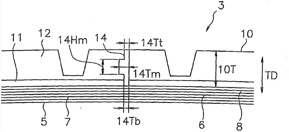
[0057] (1) In the above-mentioned embodiment, an example in which the conductive part is substantially crescent-shaped in the tire meridian section is shown, but it is not limited thereto. For example, it may be as follows: image 3 The conductive part 14 of the transverse T shape. In this conductive portion 14 , the thickness of the center portion in the thickness direction TD of the tread rubber 10 is relatively large, and the thickness of both ends of the tread rubber 10 in the thickness direction TD is relatively small.

[0058] exist image 3 In an example, the thickness 14Tm of the conductive part 14 at the center in the thickness direction TD is set to 0.6-1.5 mm, for example. In addition, the thickness 14Tt of the conductive portion 14 on the ground surface is, for example, 0.1-0.9 mm, and the thickness 14Tb of the conductive portion 14 on the bottom surface of the tread rubber 10 is, for example, 0.1-0.4 mm. In this shape, the height 14Hm of the thick portion of the...

Embodiment

[0062] Hereinafter, examples showing the configuration and effects of the present invention will be described. Each performance evaluation of the tire was performed as follows.

[0063] (1) Handling stability

[0064] Tires were mounted on an actual vehicle (1.5L class Nissan sedan), and the vehicle was driven straight or turning under the specified air pressure with the load of a single driver, and evaluated by the driver's sensory test. The results of the conventional example were evaluated as an index of 100, and a larger value indicates better steering stability.

[0065] (2) Rolling resistance

[0066] Based on the international standard ISO28580 (JISD4234), the rolling resistance at a speed of 80km / h was measured, and the reciprocal was calculated. The results of the conventional examples were evaluated as an index of 100, and a larger value indicates better rolling resistance.

[0067] (3) Wet braking performance

[0068] Install the tires on the above actual vehic...


PUM


Abstract

The invention aims at providing a pneumatic tire which can ensure operation stability and can well display effect of reducing rolling resistance and effect of improving braking performance in wet lands. The solutions are as follows: a pneumatic tire has a tread rubber (10) provided in an outer side of a carcass layer (7) in a tread portion (12). The tread rubber (10) has a cap portion (12) which is formed by a non-conductive rubber and constructs a ground-contacting surface, a base portion (11) which is provided in an inner side in the tire diametrical direction of the cap portion (12), and a conductive portion (13) which is formed by a conductive rubber and extends in a thickness direction (TD) of the tread rubber (10) so as to reach a bottom surface of the tread rubber (10) from the ground-contacting surface. A thickness of the conductive portion (13) is made relatively large in a center portion in the thickness direction (TD) of the tread rubber (10), and the thickness of the conductive portion (13) is made relatively small in both end portions in the thickness direction (TD) of the tread rubber (10).

Description

technical field [0001] The present invention relates to a pneumatic tire capable of discharging static electricity generated on a vehicle body or the tire to a road surface. Background technique [0002] In recent years, a pneumatic tire has been proposed for the purpose of reducing rolling resistance closely related to fuel consumption performance and improving braking performance on wet roads (wet braking performance). The gum is mixed with a high ratio of silica. However, this tread rubber has a high electrical resistance compared with a pneumatic tire mixed with a high proportion of carbon black, and prevents discharge of static electricity generated in the vehicle body or the tire to the road surface, and thus has the problem of easily generating troubles such as radio noise. [0003] Therefore, a pneumatic tire has been developed in which a conductive portion mixed with conductive rubber such as carbon black is embedded in a tread rubber mixed with non-conductive rubb...

Claims


Application Information

Patent Timeline
Patent Type & Authority Applications(China)
IPC IPC(8): B60C19/08
CPCB60C11/005B60C19/08B60C19/082B60C19/084Y02T10/86B60C11/0058B60C11/0075
Inventor 永井邦彦
Owner TOYO TIRE & RUBBER CO LTD
Why Eureka
Try Eureka