A card machine and parking lot charging system

A card machine and radar system technology, applied in the direction of equipment, ticketing equipment, etc., can solve the problems of complex structure of the card delivery arm, difficulty in aligning with the card outlet, difficulty in receiving the card delivery device, etc., and achieve simple structure, easy fixing, and low cost. simple effect

Active Publication Date: 2015-07-29
邳州市铁富九龙公共服务有限公司
View PDF9 Cites 0 Cited by
  • Summary
  • Abstract
  • Description
  • Claims
  • Application Information

AI Technical Summary

Problems solved by technology

However, since the card delivery device only delivers the card to the front window where the driver is, when a long-term card user needs to swipe the card to enter the parking lot, it is still difficult for human hands to reach the card sensing area. It is not very suitable for the entry card issuer and exit card reader of the card device and card issuer. In addition, due to the complex structure of the card delivery arm, the positioning accuracy is low, and the card delivery arm will reposition the card delivery device after sending the card. It is difficult to align with the card outlet when returning the position to the card outlet, which makes it difficult for the card presenter to receive the cards spit out from the card outlet, resulting in frequent failures and greatly reduced practicability

Method used


Image

  • A card machine and parking lot charging system
  • A card machine and parking lot charging system
  • A card machine and parking lot charging system

Examples


Embodiment 1

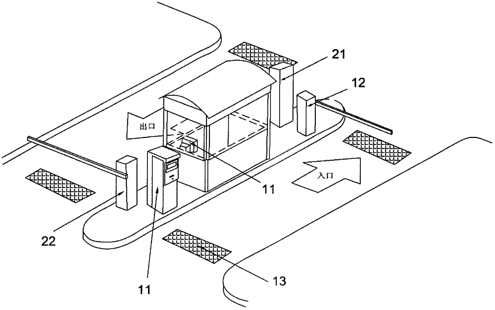
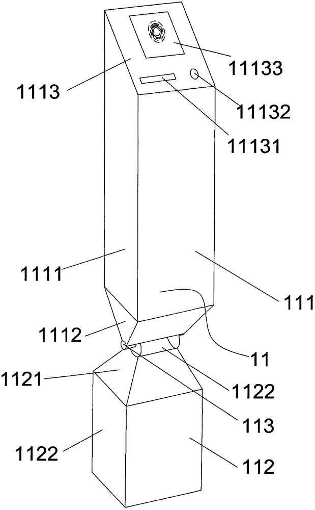
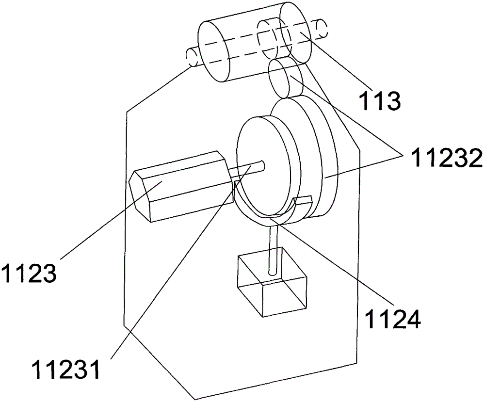
[0039] Such as figure 2 , 3 , 6, the present embodiment provides an entrance card issuing machine 11, the entrance card issuing machine 11 includes a body 111 and a base 112, the upper part 1111 of the body 111 is in the shape of a cube, and the lower part 1112 is in the shape of an inverted platform, so The upper part 1121 of the base is in the shape of a platform, and the lower part 1122 is in the shape of a cube. The lower part 1122 of the base is fixed on the ground during installation, and the upper part 1121 of the base 112 is used to support the body 111. The body 111 Swing around a rotating shaft 113 arranged between the upper part 1121 of the base and the lower part 1112 of the body, specifically: a stepping motor 1123 is fixed inside the base 112, and the motor shaft 11231 of the stepping motor 1123 is connected to the rotating shaft 113 Through gear 11232 transmission and cooperation, the rotating shaft 113 is fixedly connected with the lower end of the body 111, ...

Embodiment 2

[0047] The present embodiment provides an exit card reader 21, such as Figure 4 , 5 , 7, the exit card reader 21 includes an upper body 211 (the upper body is similar to the body of the entrance card issuer) and a lower body 212 (the lower body is similar to the base of the entrance card issuer), and the upper body of the exit card reader The body 211 includes a radio frequency card reader 2111 and a support plate 2112 for fixing and supporting the card reader 2111. The lower body 212 includes a fixing seat 2121, a fixing rod 2122 and a hydraulic rod 2123. The fixing seat 2121 is provided inside There is an oil pump 21211, the fixed rod 2122 is fixed on the top of the fixed seat 2121, the middle part of the support plate 2112 is connected with the top of the fixed rod 2122 by rotating, and the lower end of the support plate 2112 is connected to the hydraulic rod in a movable manner One end of the hydraulic rod 2123 and the other end of the hydraulic rod 2123 are connected to...


PUM


Abstract

A card machine (11) for a parking lot charging system and a parking lot charging system with the card machine (11). The card machine (11) comprises a body (111) provided with a card dispenser and / or a card reader inside. The card machine (11) further comprises a base (112) fixed on the ground. The body (111) rotates around a rotating shaft (113) arranged between the base (112) and the body (111). Accordingly, the distance between the body (111) and a side of a vehicle is shortened; people can pick cards dispensed from a card slot of the body (111) conveniently.

Description

【Technical field】 [0001] The invention belongs to the technical field of mechanical automation, and relates to a card machine for a parking lot charging system and a parking lot charging system with the card machine. 【Background technique】 [0002] The charging system of the parking lot includes entrance equipment, exit equipment and management control center. The entrance equipment includes the entrance card issuer and the electric barrier machine, and the exit equipment includes the exit card reader and the electric barrier machine. The entrance card issuer and the exit card reader are collectively referred to as card Machines are all card taking, reading or receiving equipment installed on the shoulder of the road. When the temporary vehicle enters the parking lot, the vehicle detection coil located under the driveway detects the arrival of the vehicle, and the card issuer panel at the entrance prompts the driver to press the button to take the card through the light. Th...

Claims


Application Information

Patent Timeline
Patent Type & Authority Patents(China)
IPC IPC(8): G07B15/06
CPCG07B15/04
Inventor 张庚
Owner 邳州市铁富九龙公共服务有限公司
Why Eureka
Try Eureka