Transformer bushing

A technology of transformer bushings and bushings, which is applied to transformer/inductor parts, transformer/inductor coils/windings/connections, electrical components, etc. Leakage and other problems are prone to occur, achieving the effect of great practical and promotional value, convenient testing, and reliable connection

Inactive Publication Date: 2013-05-08
JIANGSU SIYUAN HERTZ TRANSFORMER
View PDF6 Cites 5 Cited by
  • Summary
  • Abstract
  • Description
  • Claims
  • Application Information

AI Technical Summary

Problems solved by technology

Although this type of structure has excellent elasticity, due to structural reasons, it is prone to problems such as leakage and oil pollution, and after a period of operation due to temperature changes, it is prone to gas and medium accumulation. If the power failure maintenance is carried out, the maintenance cost is high, and the power consumption is affected, and the maintenance cost is high; and the existing transformer bushing can only supply power to high-power equipment after the outermost electrode tap is drawn out; with the digital circuit and intelligent With the continuous advancement of power grid requirements, when the existing equipment requires the bushing to be tested, it is necessary to transform the existing power supply or provide it to the controller through a low-power power supply to provide power for control, which makes the cost of the equipment obvious. improvement, and it is difficult to achieve the purpose of accurate testing, so it is necessary to improve the existing transformer bushing to meet the needs of smart grid

Method used


Image

  • Transformer bushing
  • Transformer bushing
  • Transformer bushing

Examples


Embodiment Construction

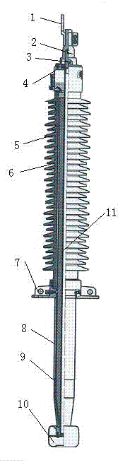
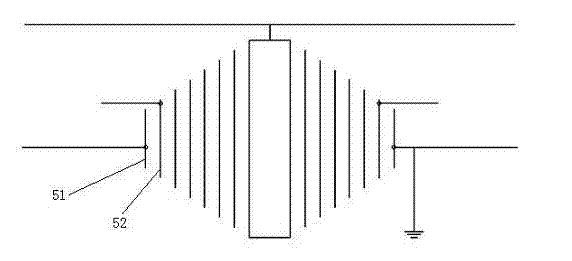
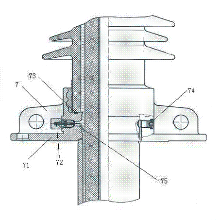
[0014] Refer to attached figure 1 , attached figure 2 , refer to attached image 3 , a transformer bushing of the present invention, which is composed of a conductive row 1, a general cap 2, a joint 3, an oil conservator 4, a bushing 5, a porcelain sleeve 6, a flange 7, a shielding bushing 8, an insulating cylinder 9, an equalizing The ball 10 and the conductive tube 11 are composed of a shielding sleeve 8 fixed on the flange 7; a pressure equalizing ball 10 is provided at the lower part of the shielding sleeve 8; a conductive tube 11 is inserted in the inner cavity of the shielding sleeve 8 A casing 5 is set on the periphery of the conductive pipe 11, and a porcelain casing 6 is set on the periphery of the casing 5. The insulating capacitor of the casing 5 is composed of an insulating medium and an electrode, and is formed by winding or dipping; The bushing 5 is an insulating capacitor provided with a plurality of lead-out taps, and the bushing 5 is an insulating capacitor...


PUM


Abstract

The invention relates to a transformer bushing used in power industries. The transformer bushing is composed of a connecting bar, a general cap, a joint, an oil pillow, a bushing, a porcelain sleeve, a flange, a shielding bushing, an insulating barrel, a voltage-sharing ball and a conducting tube, the shielding bushing is fixedly mounted on the flange, the voltage-sharing ball is arranged on the lower portion of the shielding bushing, the conducting tube is mounted in an inner cavity of the shielding bushing in an inserted manner, the bushing is mounted on the periphery of the conducting tube in a sleeved manner, the bushing is an insulating capacitor provided with multiple leading-out taps, and the lower end of the porcelain sleeve is connected with the flange. The multiple leading-out taps are arranged on the bushing and connected with a detecting device, so that detecting process can be more reliable; the taps are led out from an outermost-layer electrode and a secondary outer-layer electrode of the bushing respectively, and a low-power power source of with certain voltage can be obtained between the two electrodes during equipment running, so that a power source is provided for the detecting device; connection between test taps and the flange is reliable and compact, so that performance testing is facilitated; and grounding seats are arranged in the test taps, so that grounding is facilitated integrally.

Description

technical field [0001] The invention relates to a transformer bushing used in the power industry. Background technique [0002] After retrieving relevant patent documents, a transformer bushing with the same structure as the present invention has not yet been retrieved. The main insulation of the existing oil-paper transformer bushings is generally made of oil-immersed paper capacitor cores, which are vacuum-dried and then vacuum-wetted in the transformer. Although this type of structure has excellent elasticity, due to structural reasons, it is prone to problems such as leakage and oil pollution, and after a period of operation due to temperature changes, it is prone to gas and medium accumulation. If the power failure maintenance is carried out, the maintenance cost is high, and the power consumption is affected, and the maintenance cost is high; and the existing transformer bushing can only supply power to high-power equipment after the outermost electrode tap is drawn o...

Claims


Application Information

Patent Timeline
Patent Type & Authority Applications(China)
IPC IPC(8): H01F27/32H01F27/29H01F27/00
Inventor 杨红斌付旭明赵凯凯曾宗学何山鹏彭勇
Owner JIANGSU SIYUAN HERTZ TRANSFORMER
Why Eureka
Try Eureka