Unlock instant, AI-driven research and patent intelligence for your innovation.

Remote sensing module

A technology for measuring models and sensors, applied in the field of remote control sensing modules, which can solve the problems of scattering or diffuse sensor 11 reception, large side thickness, interference, etc., to improve the light sensing effect, reduce interference, The effect of reducing the thickness

Inactive Publication Date: 2016-03-09
QISDA SUZHOU +1
View PDF6 Cites 0 Cited by
  • Summary
  • Abstract
  • Description
  • Claims
  • Application Information

AI Technical Summary

Problems solved by technology

Therefore, with respect to the conventional design of the aforementioned remote control sensing module 100, the nested stacking method on its side will still cause the overall side thickness to be relatively large due to the large number of components or complicated assembly, thereby facilitating A thicker front frame element is required to accommodate it, and a corresponding increase in the thickness of the display is bound to be
[0008] In addition, for the operation of sensing, the structure of the optical elements 31, 32 or their lenses is necessary to achieve the purpose of filtering and concentrating light signals; however, if the remote sensing module 100 When there are still gaps or no proper blocking structure in the stacking of the various components in the system, it may cause interference to the reception of the sensor 11 due to the scattering or diffusion of the emitted light signal, making the remote control There is an error or abnormality in the sensing operation of the sensing module 100

Method used


Image

  • Remote sensing module
  • Remote sensing module
  • Remote sensing module

Examples


Embodiment Construction

[0033] In order to have a further understanding of the purpose, structure, features, and functions of the present invention, the following detailed descriptions are provided in conjunction with the embodiments.

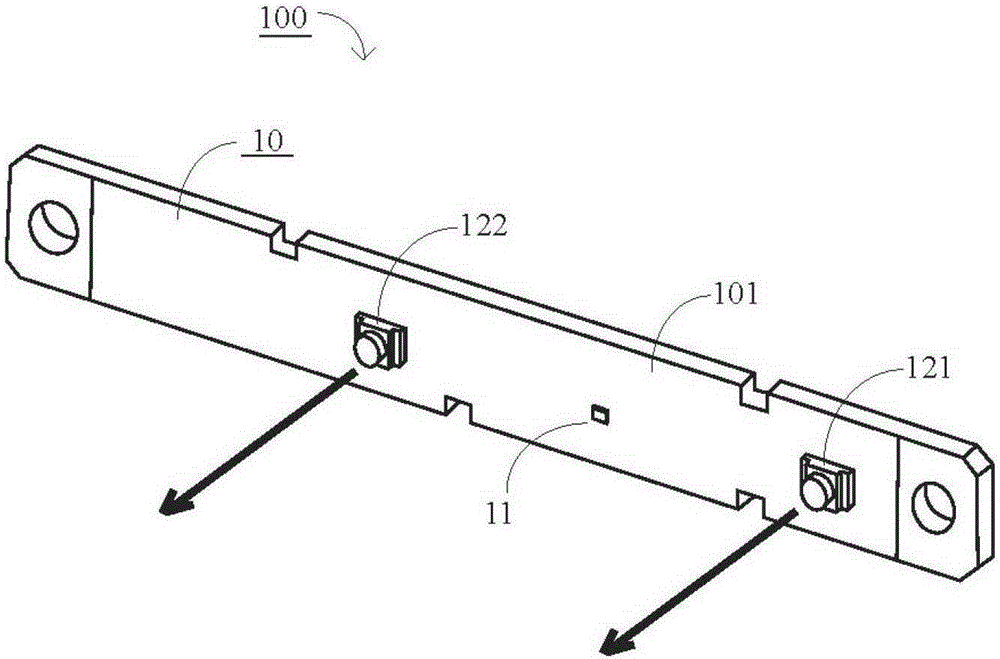
[0034] Now carry out the implementation description of the present invention with a preferred embodiment. Please refer to FIG. 3( a ). FIG. 3( a ) is an exploded view of the remote sensing module 500 of the present invention. As shown in the figure, the remote sensing module 500 is composed of a sensing plate 50 , a holding structure 60 and an optical element 70 . Wherein, the sensing plate 50 includes a circuit board 501, a sensor 51, a first emitter 521 and a second emitter 522; the sensor 51, the first emitter 521, and the second emitter 522 are arranged on the circuit board 501 On one side of the plane (that is, the other side of the plane shown in this figure), and the sensor 51 is disposed between the first emitter 521 and the second emitter 522 .

[0035]Base...


PUM


Abstract

The invention provides a remote control sensing module which comprises an immobilization structure, a sensing board and an optical element. The immobilization structure is provided with a first opening hole and a second opening hole. A first side of the immobilization structure forms a containing seat, and a second side of the immobilization structure forms at least one first protruded piece between the first opening hole and the second opening hole. The sensing board is assembled in the containing seat and provided with a circuit board, a sensing device arranged on the circuit board and a first transmitter. The sensing device and the first transmitter respectively correspond to the first opening hole and the second opening hole. The optical element is assembled on the second side of the immobilization structure and provided with a lens and at least one first groove. The lens corresponds to the first opening hole, and the first groove corresponds to the first protruded piece. The remote control sensing module reduces the thickness of a flat panel display, interference on the sensing device by light signals emitted by an infrared transmitter is avoided or reduced, and a light sensing effect is improved.

Description

technical field [0001] The invention relates to a remote control sensing module, in particular to a remote control sensing module which is arranged on a thin flat panel display and can be used for remote control or energy-saving sensing functions. Background technique [0002] Generally, the audio-visual display device of a television is usually operated by a remote controller for corresponding functions on the device. In addition to using the corresponding physical buttons to operate related functions, they can also be used to display electronic menus or screen display settings on the screen to display more functions. In addition, with the development of MEMS and semiconductor technology, a remote controller based on somatosensory remote control technology that can sense motion status has been developed. Somatosensory remote control technology is to install sensing elements in the remote control that can sense motion on three mutually perpendicular coordinate axes, such as...

Claims


Application Information

Patent Timeline
Patent Type & Authority Patents(China)
IPC IPC(8): G01D5/26
Inventor 张永烨池亭辉江进富
Owner QISDA SUZHOU