
Silicon controlled rectifier dimming circuit, silicon controlled rectifier dimming method and light emitting diode (LED) driver applied silicon controlled rectifier dimming circuit and silicon controlled rectifier dimming method

A technology of silicon dimming and LED lamps, which is applied in the direction of electric lamp circuit layout, light source, electric light source, etc., and can solve the problems of poor versatility of thyristor dimming circuits, reduced brightness range, and dimming of thyristor dimming circuits. Performance degradation and other issues, to achieve good dimming performance, high adaptability, and improve work efficiency

Active Publication Date: 2013-07-10
SILERGY SEMICON TECH (HANGZHOU) CO LTD
View PDF5 Cites 1 Cited by
  • Summary
  • Abstract
  • Description
  • Claims
  • Application Information

AI Technical Summary

Problems solved by technology

However, since the characteristic parameters of thyristor rectifier elements are different, the conduction phase angle ranges are different. For different thyristor rectifier elements, the parameters of the thyristor dimming circuit need to be adjusted differently, otherwise, it may be The dimming performance of the thyristor dimming circuit will be reduced, so the existing thyristo

Method used


Image

  • Silicon controlled rectifier dimming circuit, silicon controlled rectifier dimming method and light emitting diode (LED) driver applied silicon controlled rectifier dimming circuit and silicon controlled rectifier dimming method
  • Silicon controlled rectifier dimming circuit, silicon controlled rectifier dimming method and light emitting diode (LED) driver applied silicon controlled rectifier dimming circuit and silicon controlled rectifier dimming method
  • Silicon controlled rectifier dimming circuit, silicon controlled rectifier dimming method and light emitting diode (LED) driver applied silicon controlled rectifier dimming circuit and silicon controlled rectifier dimming method

Examples


Embodiment Construction

[0076] Several preferred embodiments of the present invention will be described in detail below with reference to the accompanying drawings, but the present invention is not limited to these embodiments. The present invention covers any alternatives, modifications, equivalent methods and schemes made on the spirit and scope of the present invention. In order to provide the public with a thorough understanding of the present invention, specific details are set forth in the following preferred embodiments of the present invention, but those skilled in the art can fully understand the present invention without the description of these details.

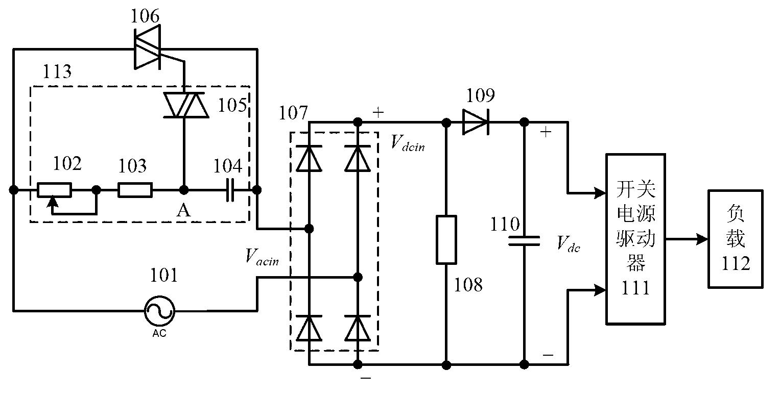
[0077] and Figure 1A different from the existing TRIAC dimming techniques shown, figure 2 The shown thyristor dimming circuit according to the first embodiment of the present invention adds a conduction phase angle signal generating circuit 201 and a dimming signal generating circuit 202 .

[0078] The conduction phase angle signal gen...


PUM


Abstract

The invention provides a silicon controlled rectifier dimming circuit, a silicon controlled rectifier dimming method and a light emitting diode (LED) driver applied the silicon controlled rectifier dimming circuit and the silicon controlled rectifier dimming method. The silicon controlled rectifier dimming circuit is used for receiving a default phased direct current voltage signal and generating a dimming signal to adjust brightness loaded by a follow-up LED light. The silicon controlled rectifier dimming circuit comprises a conductive phase angle signal generating circuit and a dimming signal generating circuit. The conductive phase angle signal generating circuit is connected with a rectifier bridge and used for receiving the default phased direct voltage signal and generating a control signal representing conductive phase angle ranges of a silicon controlled rectifier rectifying component. The dimming signal generating circuit is connected with the conductive phase angle signal generating circuit and used for receiving the control signal, an adjustable signal and a clamping voltage signal to generate a dimming signal, choosing dimming phase angle range amplitude by setting a constant value signal determined by the clamping voltage signal, and adjusting amplitude values of the dimming signal by adjusting the adjustable signal to conduct corresponding translation on a dimming phase angle range of the silicon controlled rectifier dimming circuit.

Description

[0001] This application is a divisional application with the application number of 201110089211.3 and the filing date of April 08, 2011, and the title of the invention is "a silicon controlled rectifier dimming circuit, a dimming method and an LED driver using the same". technical field [0002] The present invention relates to a dimming circuit applied to drive lamp loads, in particular to a thyristor dimming circuit, a thyristor dimming method and an LED driver using the same. Background technique [0003] For the field of lighting, since the thyristor phase control (chopper method) dimming method has the advantages of small size, reasonable price and wide range of dimming power, the thyristor phase control dimming method is currently the most widely used The dimming method is widely used in the fields of stage lighting and ambient lighting. By applying the SCR phase-controlled working principle, by controlling the conduction angle of the SCR rectifier element, a part of t...

Claims


Application Information

Patent Timeline
IPC IPC(8): H05B37/02
Inventor 徐孝如陈伟陈圣伦
Owner SILERGY SEMICON TECH (HANGZHOU) CO LTD
Learn More