

Float polishing head
A technology of polishing head and transmission shaft, which is applied in the field of floating polishing head, and can solve problems affecting the surface quality of workpieces, etc.
- Summary
- Abstract
- Description
- Claims
- Application Information
AI Technical Summary
Problems solved by technology
Method used
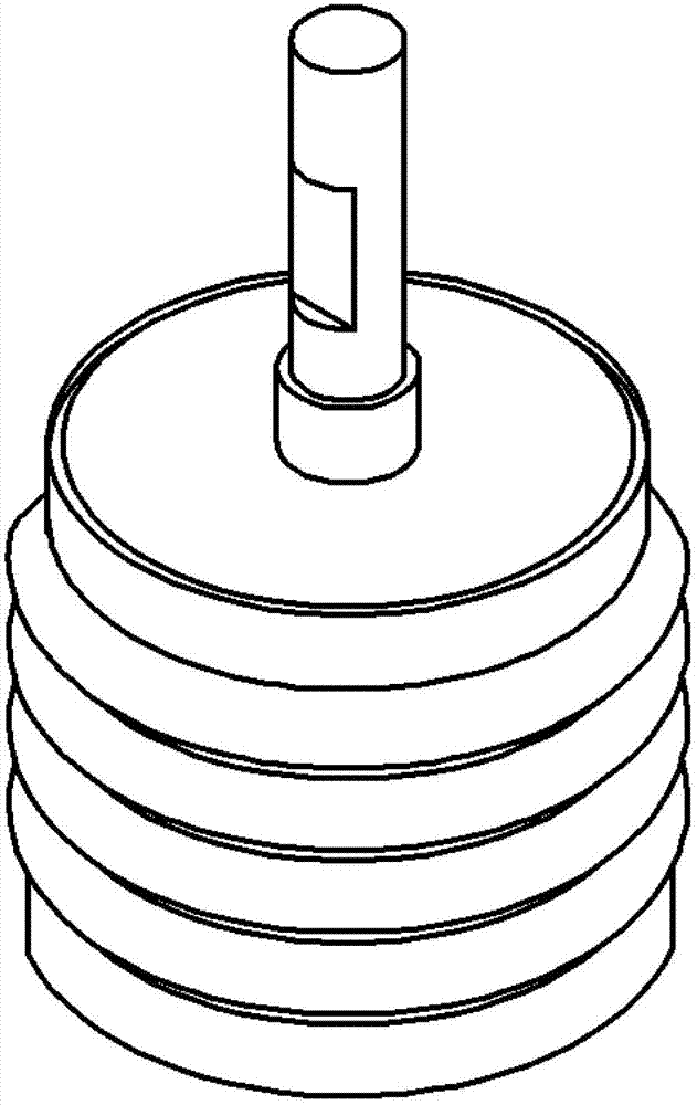
Image

Examples
Embodiment Construction
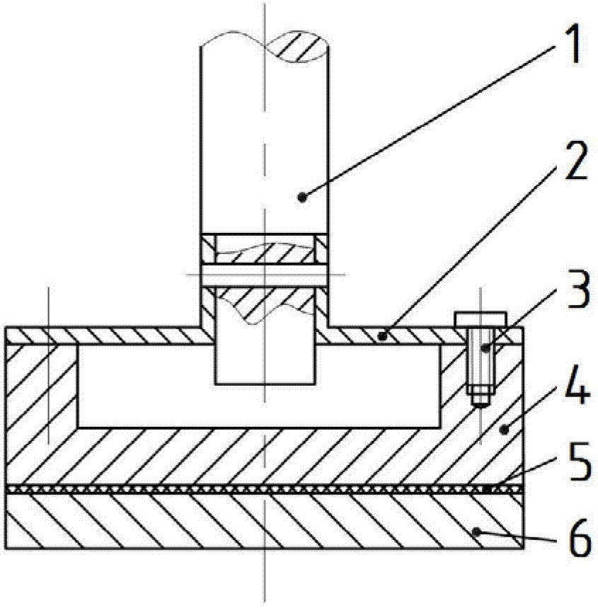
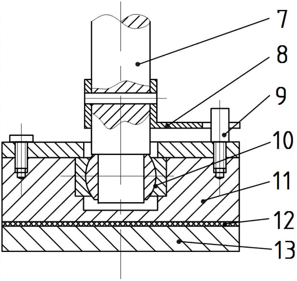
[0016] The specific embodiment of the present invention is described in detail in conjunction with technical scheme and accompanying drawing: For image 3 The shown low instantaneous center floating polishing head is composed of transmission shaft 19, upper cover 20, lower cover 25, upper ball 15, lower ball 16, upper cage 21, lower cage 17, pull rod 24, rubber bellows 23, The upper set screw 14, the lower set screw 18 and the clamping part 26 etc. are composed. The lower part of the drive shaft 19 is a spherical structure in contact with the lower ball 16, and its upper part is used to be connected to the end of the machine tool spindle. The upper cover 20 is screwed with the middle threaded locking part of the transmission shaft 19. The bottom surface of the upper cover 20 is a concave spherical surface, and there are two screw holes on the side, and the position is locked by the upper set screw 14. The lower cover 25 has two spherical structures inside and outside. The con...
PUM
 Abstract
Description
Claims
Application Information