Electronic-controlled engine, energy-saving method of electronic-controlled engine, energy-saving device of electronic-controlled engine and engineering machine

A technology of electronically controlled engines and energy-saving devices, applied in engine control, machines/engines, mechanical equipment, etc., can solve the problems of limited fuel-saving effect, high power, and no corresponding calibration of the engine, so as to achieve low transformation costs and reduce the overall cost. Energy consumption and fuel saving effect are obvious

Active Publication Date: 2013-09-04
SANY HEAVY MACHINERY
View PDF6 Cites 34 Cited by
  • Summary
  • Abstract
  • Description
  • Claims
  • Application Information

AI Technical Summary

Problems solved by technology

[0005] like figure 1 As shown, although some energy-saving schemes change the external characteristic curve of the engine according to the load, that is to say, the maximum output power of the engine is simply limited, but the specific fuel consumption curve in the universal characteristic curve of the engine is not correspondingly Calibration, that is, to reduce fuel consumption when reducing engine power
In addition, the best fuel consumption area is often close to the light load (L) mode. When the heavy load (H) is under high load, the power is high, and the corresponding fuel consumption cannot be improved. Therefore, both can not be taken into account at the same time, so the fuel saving effect is limited.

Method used


Image

  • Electronic-controlled engine, energy-saving method of electronic-controlled engine, energy-saving device of electronic-controlled engine and engineering machine
  • Electronic-controlled engine, energy-saving method of electronic-controlled engine, energy-saving device of electronic-controlled engine and engineering machine
  • Electronic-controlled engine, energy-saving method of electronic-controlled engine, energy-saving device of electronic-controlled engine and engineering machine

Examples


Embodiment Construction

[0034] The following will clearly and completely describe the technical solutions in the embodiments of the present invention with reference to the accompanying drawings in the embodiments of the present invention. Obviously, the described embodiments are only some, not all, embodiments of the present invention. Based on the embodiments of the present invention, all other embodiments obtained by persons of ordinary skill in the art without creative efforts fall within the protection scope of the present invention.

[0035] It should be noted that, in the case of no conflict, the embodiments of the present invention and the features in the embodiments can be combined with each other.
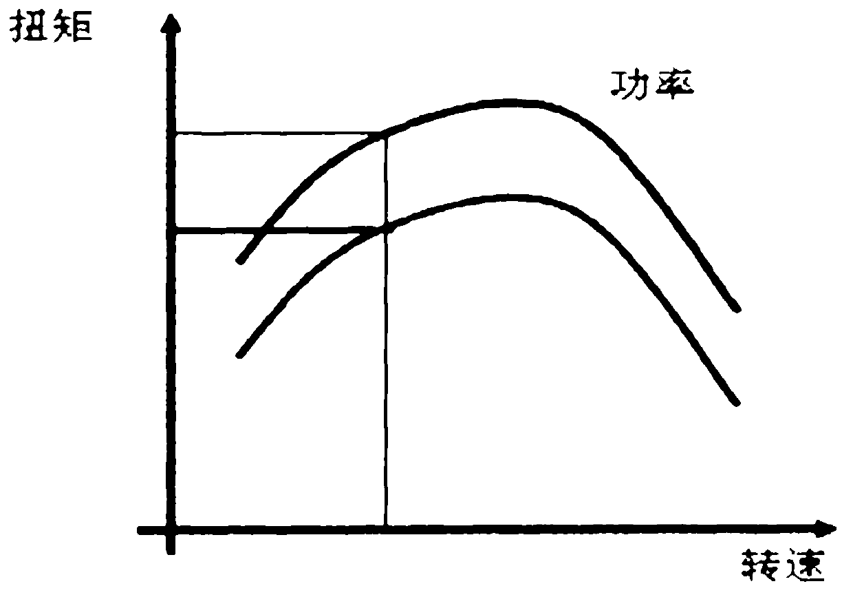
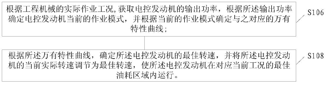
[0036] The basic idea of ​​the present invention is to design an energy-saving method for an electronically controlled engine, make a universal characteristic curve corresponding to the output power of the electronically controlled engine, and determine the corresponding universal characteristic a...


PUM


Abstract

The invention discloses an electronic-controlled engine, an energy-saving method of the electronic-controlled engine, an energy-saving device of the electronic-controlled engine and an engineering machine. The energy-saving method of the electronic-controlled engine comprises the steps of obtaining output power of the electronic-controlled engine according to actual operation working conditions of the engineering machine, determining the current operation mode of the electronic-controlled engine according to the output power, determining an universal characteristic curve corresponding to the current operation mode according to the current operation mode, according to the universal characteristic curve, determining the optimal rotation speed of the electronic-controlled engine, adjusting the current actual rotation speed of the electronic-controlled engine into the optimal rotation speed, and enabling the electronic-controlled engine to operate in an optimal oil consumption area corresponding to the current working condition. Therefore, the optimal oil consumption area can be correspondingly set according to loads, and the purpose of effectively reducing energy consumption of the whole engine can be achieved according to the working condition with different loads.

Description

technical field [0001] The invention relates to the field of construction machinery, in particular to an electronically controlled engine, an energy-saving method, an energy-saving device and construction machinery. Background technique [0002] With the development of the global economy, construction machinery has achieved unprecedented development. Among them, although hydraulic excavators can perform various operations with high power and high sensitivity, the total utilization rate of their energy is only about 20%, and the huge energy loss makes energy saving Technology becomes the main topic at present. Among them, the engine is the power source of the excavator. With the increasing awareness of environmental protection in the world, more and more Euro Ⅲ and Euro Ⅳ electronically controlled engines are installed. mainstream of the system. [0003] At present, most traditional excavators use mechanical fuel system engines. According to different operating conditions, ...

Claims


Application Information

Patent Timeline
Patent Type & Authority Applications(China)
IPC IPC(8): F02D29/00
Inventor 曹东辉陈克雷石向星
Owner SANY HEAVY MACHINERY
Why Eureka
Try Eureka