Pendulum for Micro Rotor Dynamic Balancing Machine

A technology of dynamic balancing machine and micro-rotor, which is applied in static/dynamic balance testing, machine/structural component testing, measuring devices, etc., and can solve the problem of small forced vibration acceleration amplitude of pendulum racks, unbalance measurement accuracy, and reduced Sensitivity and other issues to achieve the effect of ensuring the swing amplitude, improving accuracy and improving sensitivity

Active Publication Date: 2016-06-01
HENAN UNIV OF SCI & TECH
View PDF8 Cites 0 Cited by
  • Summary
  • Abstract
  • Description
  • Claims
  • Application Information

AI Technical Summary

Problems solved by technology

Four elastic rods 1-2 are used as supports in the swing frame, and the rigidity of the elastic rods 1-2 cannot be too small, otherwise the swing frame cannot be supported. When the support block is rotated by the pressure of the micro rollers, the excessive rigidity of the elastic rod will interfere with the horizontal swing of the support block, resulting in a decrease in the swing amplitude of the support block, reducing the sensitivity of the entire pendulum in the measurement of dynamic unbalance, resulting in unbalance reduction in measurement accuracy
For example, the mass of the whole pendulum frame is more than 100g, but for the miniature rollers whose mass is less than 10g, the unbalanced force caused by the unbalanced amount of the miniature rollers is very small, so the forced excitation of the pendulum frame is also very small, so that the pendulum frame The mass of the pendulum is several times that of the miniature rollers, and the acceleration amplitude of the forced vibration of the pendulum is very small, which cannot be accurately measured

Method used


Image

  • Pendulum for Micro Rotor Dynamic Balancing Machine
  • Pendulum for Micro Rotor Dynamic Balancing Machine
  • Pendulum for Micro Rotor Dynamic Balancing Machine

Examples


Embodiment Construction

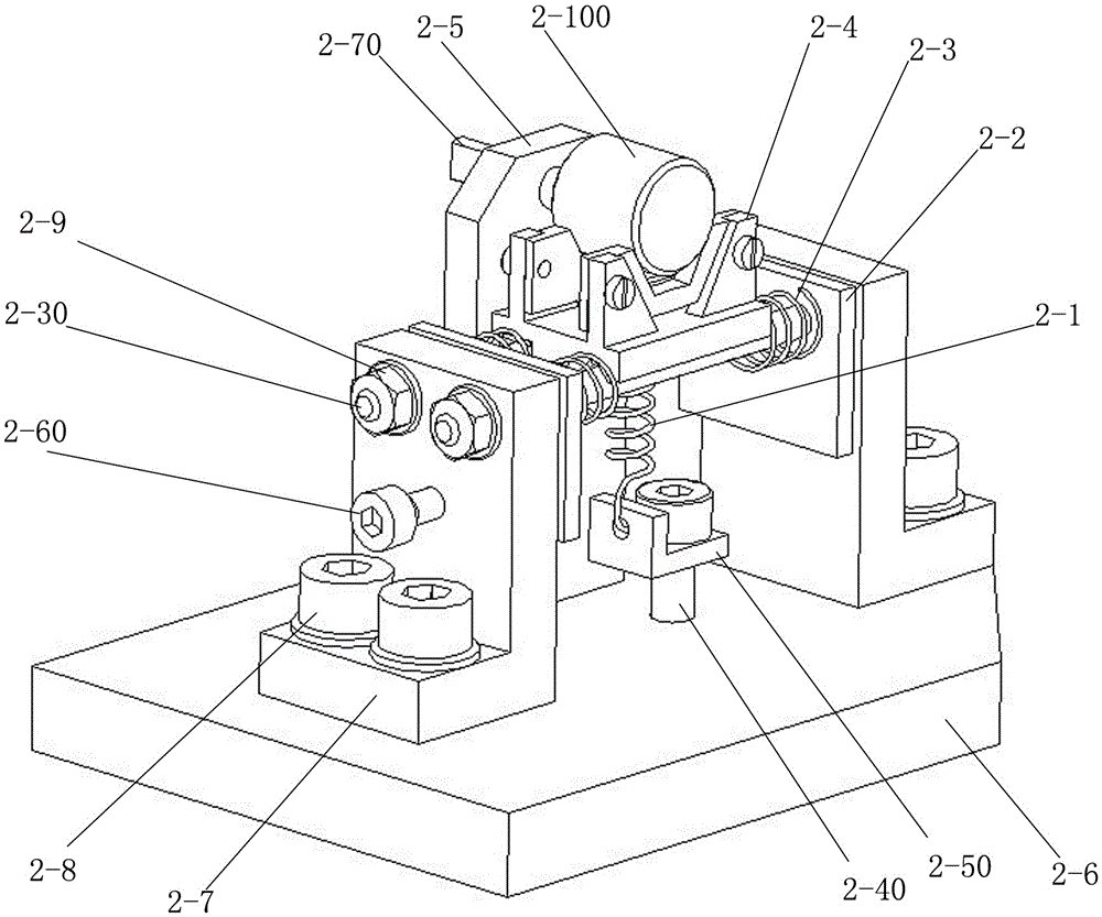
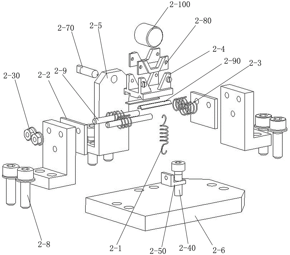
[0022] The embodiment of pendulum for miniature rotor dynamic balancing machine of the present invention: as Figure 2 to Figure 7 As shown, the pendulum for the miniature rotor dynamic balancing machine is suitable for measuring the dynamic balance of the short and small miniature rollers of the height bearing. Spring 2-3, support block 2-4 and thimble seat 2-5, wherein frame comprises plate-shaped base 2-6 and L-shaped guide rail support 2-7, and guide rail support 2-7 has two, and The left and right sides of the base 2-6 are fixed on the left and right sides of the base 2-6 symmetrically by the fastening screws 2-8. The two ends of the guide rod pass through the opposite sides of the two guide rail supports 2-7, and the outer circumference of the passing part is screwed with a fastening nut 2-9, so that the two guide rods are fixedly bridged on the two guide rail supports. Between 2-7. The support block is integrally connected by a plate-shaped guide seat 2-10 and a V-sha...


PUM


Abstract

The invention discloses a swing frame for a mini-sized rotor dynamic balancing machine. A machine frame of the swing frame is a rigidity guide frame which is fixedly arranged; the machine frame is matched with supporting blocks in a guiding mode at a horizontally swinging linear direction of the supporting blocks through a guide mechanism; the guide mechanism comprises the machine frame, guide rods and guide channels; the guide rods and the guide channels are correspondingly formed on the supporting blocks and extend along the swing direction of the supporting blocks; the number of the guide blocks is at least two; the guide rods are separately arranged by two guide rods; the guide channels and the guide rods are arranged in a one-to-one correspondence mode; damping devices are damping units which are arranged at two back-to-back sides of the swing direction of the supporting blocks in an elastic damping check mode. Accordingly, the existing machine frame which has an elastic supporting function is replaced by the rigidity machine frame, the frame self-rigidity influence to guide swing of supporting blocks is reduced through guide movement of the supporting blocks on the machine frame, and the sensitivity of the integral swing frame during the processing of measuring the mini-sized rotor dynamic imbalance performance is improved.

Description

technical field [0001] The invention relates to a swing frame for a dynamic balancing machine used in the dynamic balance measurement of a micro rotor. Background technique [0002] At present, with the continuous development of high-speed rolling bearings in the direction of high speed, the United States put high DN value (2.5 ~ 3.0) × 10 30 years ago 6 [mm×(r / min)] Spindle bearing research is listed as a key pre-research project, and during the "Ninth Five-Year Plan" period in my country, the DN value of 2.5×10 was also carried out for roller bearings. 6 experimental research. According to statistics, under the condition of high DN value, the main cause of failure of high-speed rolling bearings is no longer fatigue spalling, but surface damage and corrosion accounting for more than 70% of the total failure rate, which is the main cause of surface damage and corrosion It lies in high-speed light-load skid scratches, high-temperature jamming, cage fracture, wear, etc. Cor...

Claims


Application Information

Patent Timeline
Patent Type & Authority Patents(China)
IPC IPC(8): G01M1/02
Inventor 李济顺隋新薛玉君司东宏李丽红刘春阳杨芳潘为民刘义姜海军
Owner HENAN UNIV OF SCI & TECH
Why Eureka
Try Eureka