Coupler knuckle push iron, railway vehicle coupler and railway vehicle

A technology of knuckle tongue and hook body, which is applied to railway car body parts, railway couplings, transportation and packaging, etc., to achieve the effects of improving strength, optimizing layout and improving safety

Active Publication Date: 2013-12-04
CHINA RAILWAYS CORPORATION +1
View PDF6 Cites 13 Cited by
  • Summary
  • Abstract
  • Description
  • Claims
  • Application Information

AI Technical Summary

Problems solved by technology

[0005] Figure 7 Yes figure 2 Schematic diagram of removing the knuckle and knuckle pushing iron in ; figure 2 , Figure 4 and Figure 7 As shown, since the kicking leg portion 31 and the lock seat portion 32 of the knuckle push iron 3 in the prior art are coplanar, the horizontal rotation area of ​​the kick leg portion 31 and the lock seat portion 32 occupies the inner space of the hook body 1. Most of the space at the bottom of the cavity, and the lower traction platform 104 of the hook body 1 is formed on the bottom surface of the cavity in the hook body 1. Under such a layout, the extension length of the lower traction platform 104 along the horizontal

Method used


Image

  • Coupler knuckle push iron, railway vehicle coupler and railway vehicle
  • Coupler knuckle push iron, railway vehicle coupler and railway vehicle
  • Coupler knuckle push iron, railway vehicle coupler and railway vehicle

Examples


Embodiment Construction

[0022] "Longitudinal" described in the present invention refers to the direction in which the rail extends; "front" refers to the running direction of the train; When the leg rotates around the push iron pin in the horizontal plane, the vertical projection of the kick leg when it is rotated to the maximum angle position relative to the longitudinal direction, and the vertical projection of the kick leg when it is rotated to the minimum angle position relative to the longitudinal direction, is when The longitudinal projection of the position of the kick leg when the coupler is in the locked and fully open states respectively.

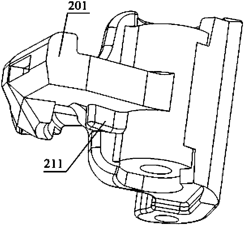
[0023] Figure 8 It is a perspective view of the tongue pushing iron in the railway vehicle coupler embodiment of the present invention; please refer to Figure 8 , the present embodiment provides a knuckle pusher, including: a pusher pin 73 vertically arranged for hinged connection with the hook body, and the pusher pin 73 is respectively fixedly provi...


PUM


Abstract

The invention provides a piece of coupler knuckle push iron, a railway vehicle coupler and a railway vehicle. The piece of coupler knuckle push iron comprises a push iron pin shaft arranged in the perpendicular direction and used for being hinged to a coupler body, wherein a leg kicking portion and a locking base are respectively and fixedly arranged on the push iron pin shaft, the leg kicking portion is used for driving a coupler knuckle to horizontally rotate, and the locking base is matched with a piece of locking iron. The distance between the lower surface of the leg kicking portion and the lower surface of the locking base is a first distance. According to the piece of coupler knuckle push iron, when the push iron pin shaft rotates, in a vehicle coupler body of the piece of the coupler knuckle push iron, the horizontal rotating area of the leg kicking portion is arranged above the top face of a lower traction table, therefore, the strength of the coupler body can be improved by increasing the extending length of the lower traction table of the coupler body, the aim of optimizing the layout in the coupler body is achieved, meanwhile, the possibility that the lower traction table of the coupler body is cracked even broken is reduced, and the safety of operation of the railway vehicle is improved.

Description

technical field [0001] The invention relates to the manufacturing technology of railway vehicles, in particular to a coupler tongue push iron, a railway vehicle coupler and a railway vehicle. Background technique [0002] The coupler is an important part of the coupler buffer device. Its function is to realize the connection between the railway locomotive and the carriage or between the carriage and the carriage, transmit the traction force and the impact force, and keep a certain distance between the two adjacent carriages. [0003] figure 1 is a structural schematic diagram of the prior art coupler in the main viewing direction, figure 2 yes figure 1 Middle A-A sectional view, image 3 is a perspective view of a knuckle in a prior art coupler, Figure 4 It is a three-dimensional view of the knuckle pushing iron in the coupler of the prior art, Figure 5 It is a schematic diagram of the transmission relationship between the knuckle pushing iron and the knuckle in the ...

Claims


Application Information

Patent Timeline
IPC IPC(8): B61G3/10
Inventor 孟庆民姜岩赵天军崔英俊王长春于跃斌魏鸿亮胡海滨
Owner CHINA RAILWAYS CORPORATION
Why Eureka
Try Eureka