Fixing shifting fork for caterpillar links

A technology of chain rail links and shifting fork shafts is applied in the field of processing chain rail link fixtures, which can solve the problems of easy wear and service life of the ends, and achieve the effects of increasing service life, reasonable structure design and small volume.

Inactive Publication Date: 2014-01-01
KUNSHAN KAINUOER METAL PROD
View PDF7 Cites 0 Cited by
  • Summary
  • Abstract
  • Description
  • Claims
  • Application Information

AI Technical Summary

Problems solved by technology

[0003] The purpose of the present invention is to propose a fixed shift fork for chain rail links, which solves the problem that the end of the existing shift fork claw is easy to wear and has a short service life

Method used


Image

  • Fixing shifting fork for caterpillar links
  • Fixing shifting fork for caterpillar links

Examples


Embodiment Construction

[0016] In order to make the object, technical solution and advantages of the present invention clearer, the present invention will be further described in detail below in conjunction with the accompanying drawings and embodiments. It should be understood that the specific embodiments described here are only used to explain the present invention, not to limit the present invention.

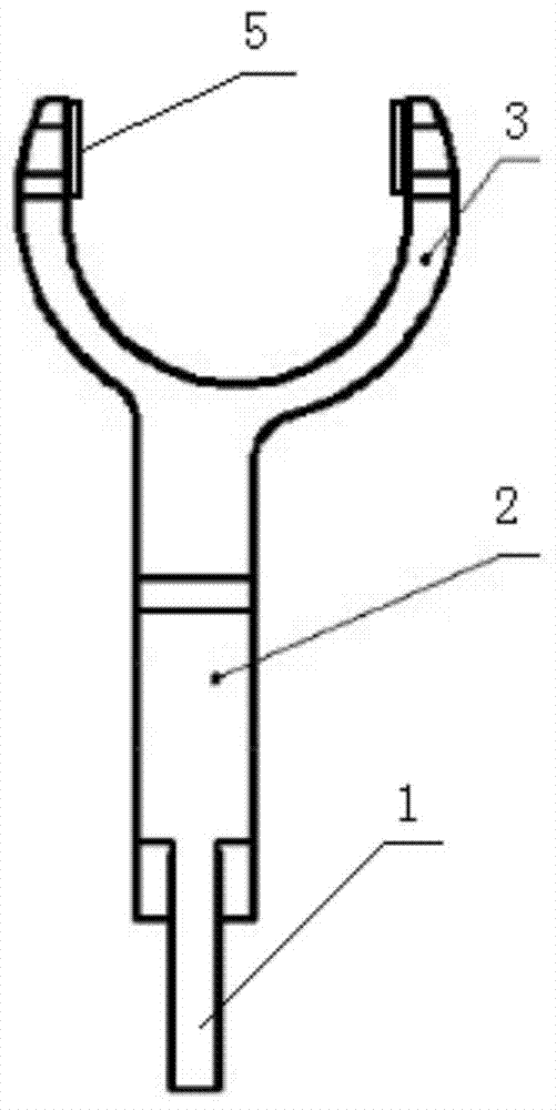
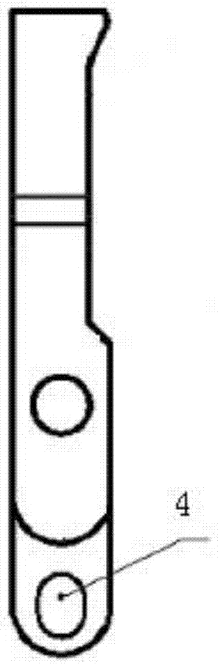
[0017] See figure 1 figure 2 , a chain track link fixed shift fork in this embodiment, including a shift fork handle 1, a shift fork shaft 2, and a shift fork claw 3, the shift fork claw 3 is a U-shaped structure, and the end of the shift fork claw 3 is set There is a protrusion 5, the shift fork shaft 2 is eccentrically and vertically fixed below the shift fork claw 3, and the shift fork handle 1 is connected with the shift fork shaft 2.

[0018] By designing the shift fork claw 3 into a U-shaped structure, the end of the shift fork claw 3 is in contact with the workpiece. The support pressure ...


PUM


Abstract

The invention relates to the technical field of caterpillar link clamp machining and particularly relates to a fixing shifting fork for caterpillar links. The fixing shifting fork comprises a shifting fork shank, a shifting fork shaft and a U-shaped shifting fork claw. Protrusions are arranged at ends of the shifting fork claw, the shifting fork shaft is fixed below the shifting fork claw eccentrically and perpendicularly, and the shifting fork shank is connected with the shifting fork shaft. According to the fixing shifting fork, the fixing shifting fork comprises the shifting fork shank, the shifting fork shaft and the shifting fork claw, the shifting fork claw is U-shaped, to that a workpiece can be tightly pressed, tool crashing caused by the fact that the workpiece cannot be pressed tightly is effectively prevented; the protrusions are arranged at ends of the shifting fork claw, so that abrasion of the ends of the shifting fork claw is prevented, and the service life is prolonged; the shifting fork shaft is fixed below the shifting fork claw eccentrically and perpendicularly, and the shifting fork shank is connected with the shifting fork shaft, so that the fixing shifting fork is reasonable in structural design, small in size and simple to exchange and operate.

Description

technical field [0001] The invention relates to the technical field of clamps for processing chain rail links, in particular to a chain rail link fixing shift fork. Background technique [0002] In the design of the chain rail link fixture, there was no fork structure at first, but after long-term processing and application practice, it was found that the chain rail link tended to tilt outward when placing the workpiece, and even fell directly outward when the workpiece was placed. If the workpiece falls outward, the rotating arm will not be able to press the workpiece correctly, resulting in knife collision or even quality accidents. In order to overcome this problem, there has been a chain rail link fixed fork that effectively prevents the workpiece from toppling outwards. However, the end of the fork claw of this kind of fork is in contact with the workpiece, and the supporting pressure of the end contact is large, which is easily worn or even Cracking, resulting in a sh...

Claims


Application Information

Patent Timeline
Patent Type & Authority Applications(China)
IPC IPC(8): B23Q3/00
CPCB23Q3/00
Inventor 戎海明
Owner KUNSHAN KAINUOER METAL PROD
Why Eureka
Try Eureka