Conveyor belt system and conveyor belt

A technology for conveyor belts and belt sections, applied in the direction of conveyors, transportation and packaging, etc., which can solve problems such as increased friction, and achieve the effects of improved elongation characteristics, small shape changes, and easy shape changes

Inactive Publication Date: 2014-03-05
THYSSENKRUPP RESOURSE TECH GMBH
View PDF12 Cites 9 Cited by
  • Summary
  • Abstract
  • Description
  • Claims
  • Application Information

AI Technical Summary

Problems solved by technology

Although tilting the axis of rotation with respect to the lateral direction of the belt produces some centering effect, a significant increase in friction occurs simultaneously, significantly increasing wear and the drive energy required to advance the belt

Method used


Image

  • Conveyor belt system and conveyor belt
  • Conveyor belt system and conveyor belt
  • Conveyor belt system and conveyor belt

Examples


Embodiment Construction

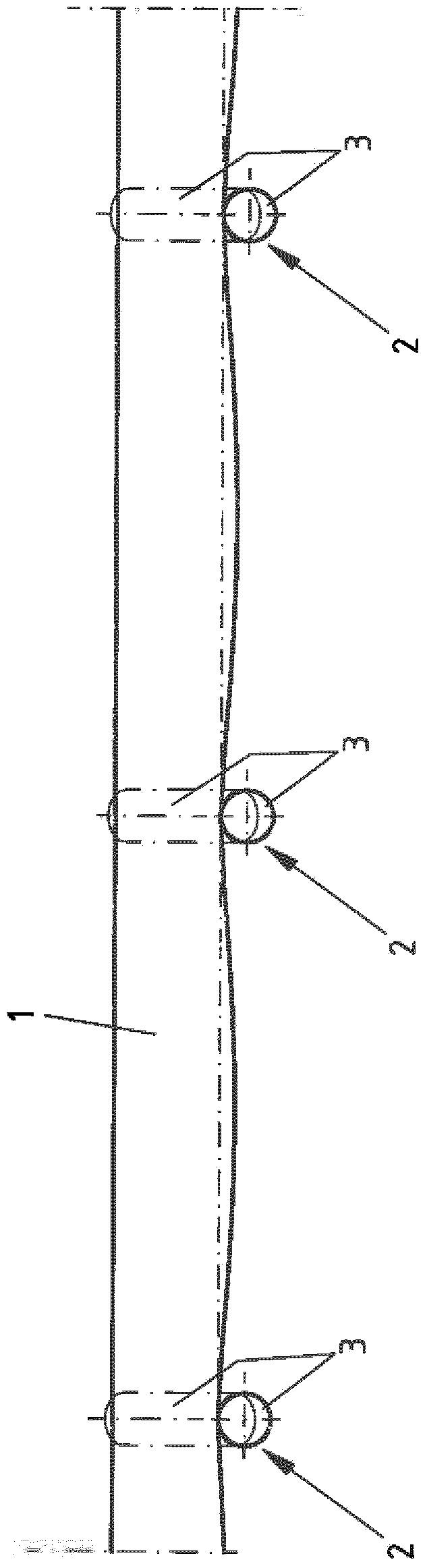
[0034] figure 1 A side view is provided depicting a trough section of a conveyor belt system wherein a conveyor belt 1 extends in the longitudinal direction and a plurality of support roller brackets 2 are spaced apart in the longitudinal direction against which the conveyor belt 1 is supported on support rollers 3. As shown here, the lower edge of the conveyor belt 1 hangs down between the support roller brackets 2 with respect to the horizontal position. The conveyor belt 1 can be designed as a continuous rotating belt, in which the conveyor belt 1 moving back and forth is guided in opposite directions in two planes, one of which lies above the other. However, for reasons of clarity, only the upper part running with the corresponding support rollers 3 is shown.

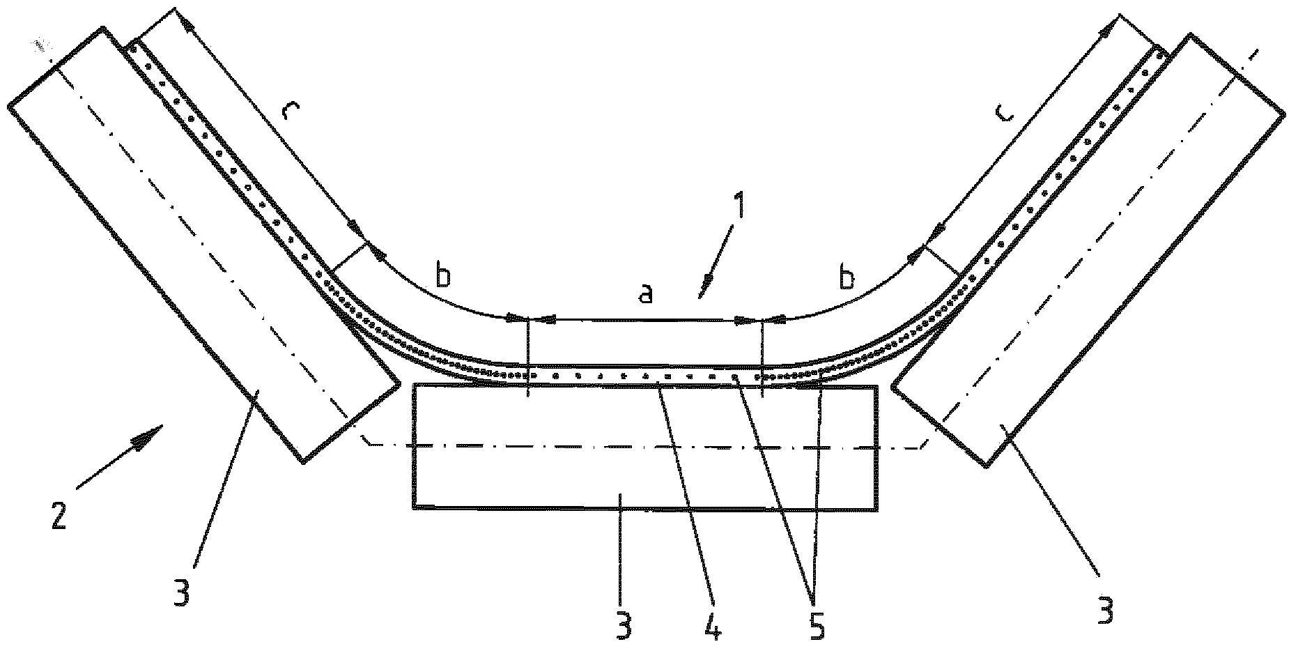
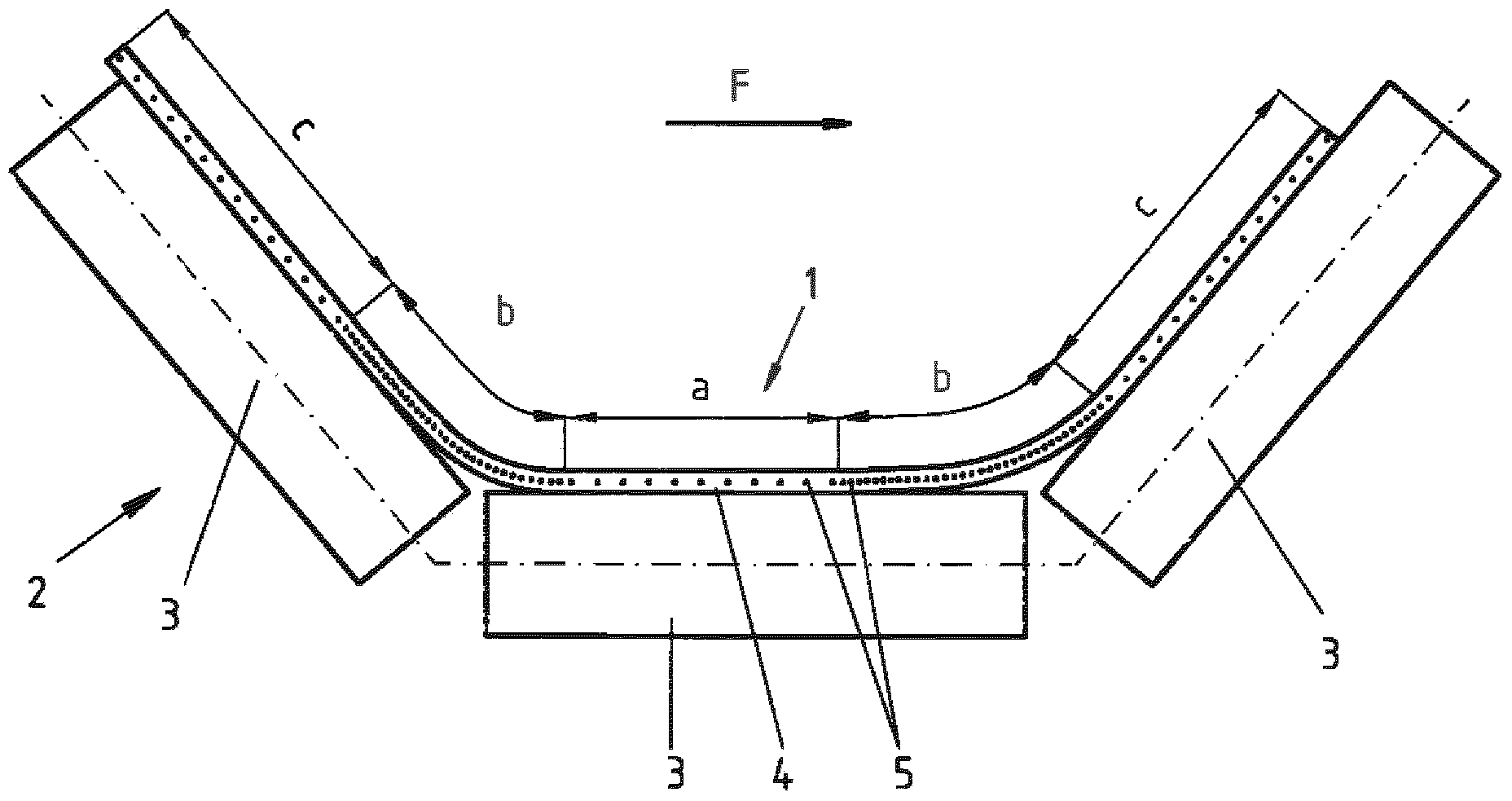
[0035] FIG. 2 a shows a cross section through the conveyor belt 1 in the region of a support roller bracket 2 for the conveyor belt system according to the invention. As shown, the exemplary embodiment shows that...


PUM


Abstract

The invention relates to a conveyor belt system comprising a conveyor belt (1) extending in the longitudinal direction and a plurality of support roller stations (2) arranged at a distance from each other in the longitudinal direction and on which the conveyor belt (1) is supported by support rollers (3), said conveyor belt (1) being formed from a flexible base material (4) and a plurality of unconnected traction means (5) which determine the tensile strength of the conveyor belt (1) and which extend in the longitudinal direction. According to the invention, in the cross-section of the conveyor belt (1) and with respect to a desired position on a central belt section (a) supported on a support roller (3) of the support roller station (2), the tensile strength relative to the belt width is less than on the laterally adjoining belt sections (b) which are not supported in the desired position by a support roller (3). The invention also relates to the conveyor belt (1) itself.

Description

technical field [0001] The invention relates to a conveyor belt system having a conveyor belt extending in the longitudinal direction and a plurality of support roller brackets spaced apart from each other in the longitudinal direction, the conveyor belt being supported by support rollers on the support roller brackets, wherein the conveyor belt is supported by flexible The base material and a plurality of unconnected traction means extend in the longitudinal direction and determine the tensile strength and the tensile stiffness of the conveyor belt in its longitudinal direction. The traction means, also referred to as reinforcement, are usually embedded in the base material and form the basic frame, which is also referred to as the casing. Within the scope of the present invention, the center alignment of the conveyor belt in cross-section on the support roller bracket is referred to as the desired position. The subject of the invention is also a conveyor belt. For example,...

Claims


Application Information

Patent Timeline
Patent Type & Authority Applications(China)
IPC IPC(8): B65G15/36B65G15/40
CPCB65G15/36B65G15/40B65G15/08
Inventor V·若兹
Owner THYSSENKRUPP RESOURSE TECH GMBH
Why Eureka
Try Eureka