Four-position seven-way reversing valve

A reversing valve, valve body technology, applied in multi-way valves, valve details, valve devices, etc., can solve the problems of inability to realize the rotation function and the inability to realize multi-channel rotation, so as to save the circuit connection and control components, The effect of improving diversity and expanding application fields

Active Publication Date: 2015-10-28
无锡气动技术研究所有限公司
View PDF7 Cites 1 Cited by
  • Summary
  • Abstract
  • Description
  • Claims
  • Application Information

AI Technical Summary

Problems solved by technology

[0002] In the pneumatic system, the manual rotary valve is a widely used component in the pneumatic circuit as a manual control reversing element. It drives the manual shaft through the handle to reversing the reversing valve core. There are two arc-shaped flow channels on the reversing valve core. After turning the direction, the four air ports of the corresponding lower valve body realize the position conversion. There is a through hole on the reversing valve core to conduct the airflow to act on the top of the valve core, and press the reversing valve core to form a sealing surface, so as to realize the three positions of the manual rotary valve. At present, the same structural design is adopted at home and abroad, but this structure has a limitation, it can only rotate and control the reversing within the specified design angle range, and cannot realize other directions within the circumference range. Direction rotation function, and it is impossible to continuously rotate and conduct multiple channels in different directions according to the specified indexing angle

Method used


Image

  • Four-position seven-way reversing valve
  • Four-position seven-way reversing valve
  • Four-position seven-way reversing valve

Examples


Embodiment Construction

[0028] The present invention will be further described below in conjunction with specific examples.

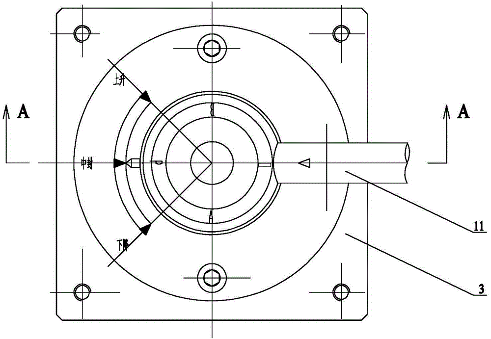
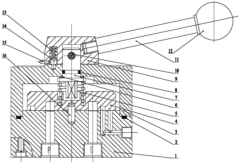
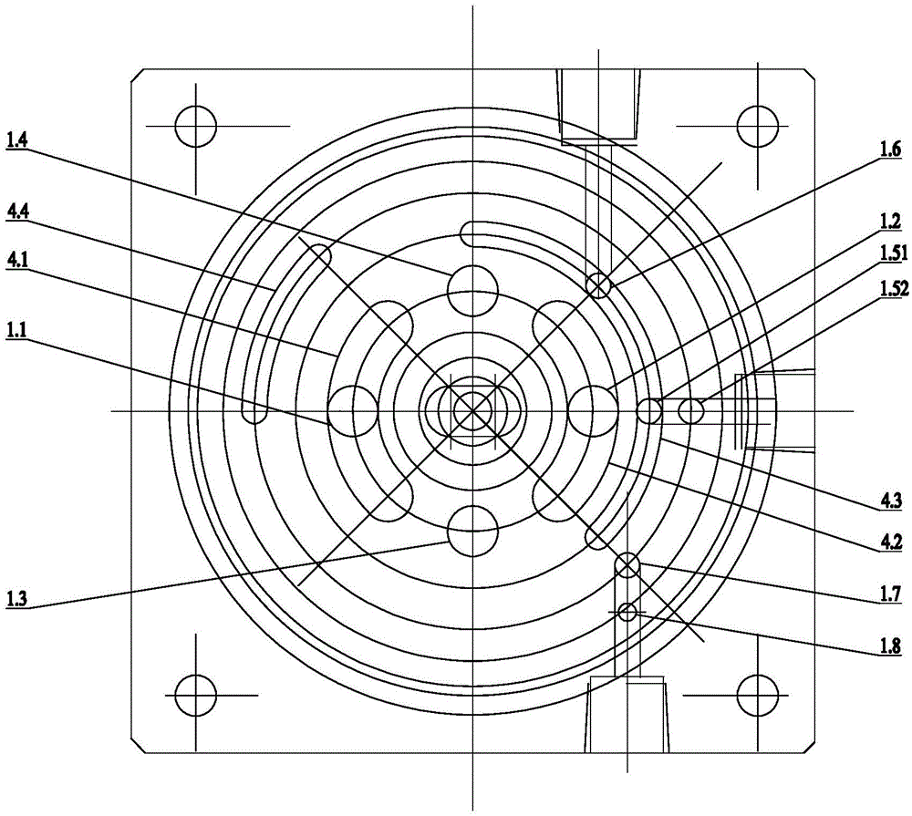
[0029] The four-position, seven-way reversing valve includes a lower valve body 1, an intermediate valve body 3, and an upper valve body 9. An intermediate valve body 3 is sealed and fixed on the upper surface of the lower valve body 1, and a reversing valve body is arranged in the intermediate valve body 3. The spool 4 and the compression spring 5, the upper end of the compression spring 5 is against the top of the inner wall of the middle valve body 3, the lower end of the compression spring 5 is against the upper surface of the reversing spool 4, and the upper end of the reversing spool 4 The lower surface is pressed against the upper surface of the lower valve body 1, an upper valve body 9 is rotated on the upper surface of the middle valve body 3, a rotating shaft 7 is fixed on the upper valve body 9, and a rotating shaft is installed on the middle valve body 3. Hole, rot...


PUM


Abstract

The invention relates to a four-position seven-way reversing valve. A middle valve body is fixed on the upper surface of a lower valve body in a sealing mode; a reversing valve core and a pressure spring are arranged inside the middle valve body; the upper end portion of the pressure spring is abut against the top of the inner wall of the middle valve body; the lower end portion of the pressure spring is abut against the upper surface of the reversing valve core; the lower surface of the reversing valve core and the upper surface of the lower valve body are compressed; an upper valve body is installed on the upper surface of the middle valve body in a rotating mode; a rotating shaft is fixed on the upper valve body; a rotating shaft installation hole is formed in the middle valve body; the rotating shaft is rotationally installed inside the rotating shaft installation hole in a sealing mode; the lower end portion of the rotating shaft and the reversing valve core are fixed. According to the four-position seven-way reversing valve, a four-position seven-way control loop is achieved, simultaneously controlled continuous movement of a multi-gas-circuit of an automatic production line is achieved, application area of a pneumatic system is expanded to a large extent, diversity, practicability and quickness of a pneumatically controlled loop are improved, and loop connecting and controlling elements are saved.

Description

technical field [0001] The invention relates to a reversing valve body, in particular to a four-position, seven-way reversing valve. Background technique [0002] In the pneumatic system, the manual rotary valve is a widely used component in the pneumatic circuit as a manual control reversing element. It drives the manual shaft through the handle to reversing the reversing valve core. There are two arc-shaped flow channels on the reversing valve core. After turning the direction, the four air ports of the corresponding lower valve body realize the position conversion. There is a through hole on the reversing valve core to conduct the airflow to act on the top of the valve core, and press the reversing valve core to form a sealing surface, so as to realize the three positions of the manual rotary valve. At present, the same structural design is adopted at home and abroad, but this structure has a limitation, it can only rotate and control the reversing within the specified de...

Claims


Application Information

Patent Timeline
Patent Type & Authority Patents(China)
IPC IPC(8): F16K11/074F16K27/04F16K37/00
CPCF16K11/074F16K27/045F16K37/0016
Inventor 王春丽张连仁曹迎杨飞飞
Owner 无锡气动技术研究所有限公司
Why Eureka
Try Eureka