Array electromagnetic shielding optical window with three-period externally-tangent circular rings and internally-tangent sub circular rings

An electromagnetic shielding and ring array technology, applied in the direction of magnetic/electric field shielding, electrical components, etc., can solve the problems of low imaging quality, concentrated stray light distribution, etc., and achieve the effect of improving electromagnetic shielding effect and improving uniformity

Active Publication Date: 2015-06-17
HARBIN INST OF TECH
View PDF12 Cites 0 Cited by
  • Summary
  • Abstract
  • Description
  • Claims
  • Application Information

AI Technical Summary

Problems solved by technology

[0019] The purpose of the present invention is to overcome the deficiencies of the above-mentioned existing optical window electromagnetic shielding technical solutions, especially for the existence of advanced To solve the problem of relatively concentrated stray light distribution caused by sub-diffraction, an electromagnetic shielding light window with a three-period circumscribed ring and inscribed sub-ring array was developed to achieve depth homogenization of high-order diffraction and extremely low impact on imaging quality the goal of

Method used


Image

  • Array electromagnetic shielding optical window with three-period externally-tangent circular rings and internally-tangent sub circular rings
  • Array electromagnetic shielding optical window with three-period externally-tangent circular rings and internally-tangent sub circular rings
  • Array electromagnetic shielding optical window with three-period externally-tangent circular rings and internally-tangent sub circular rings

Examples


Embodiment Construction

[0055] The present invention is further described below with reference to accompanying drawing and preferred embodiment:

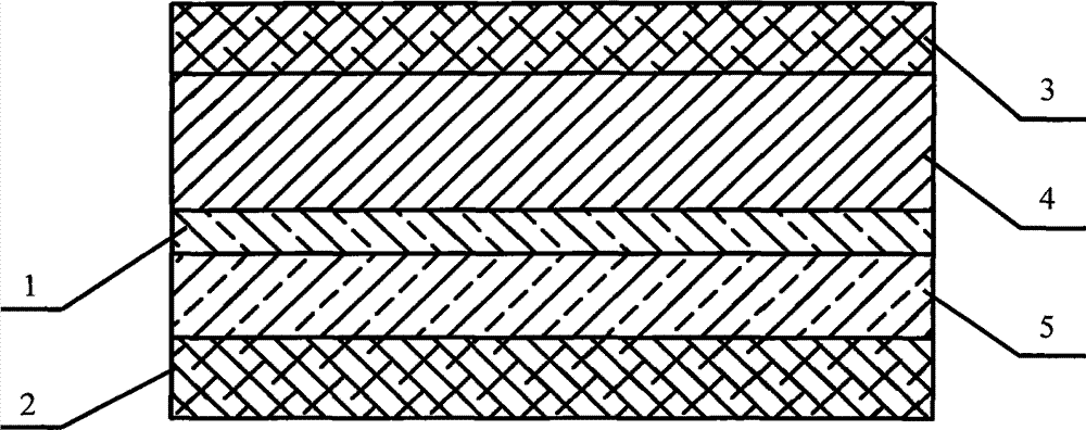
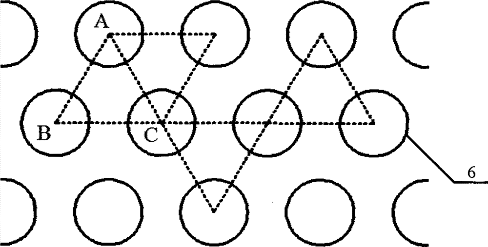
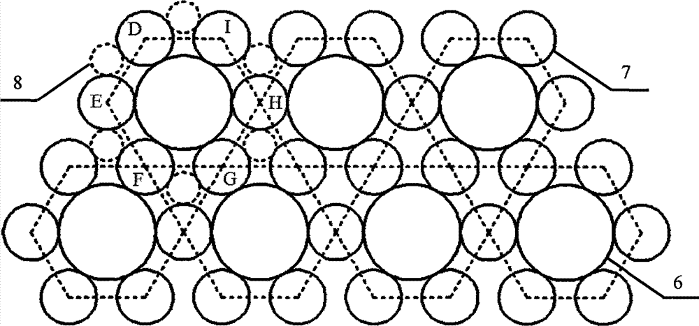
[0056] An electromagnetic shielding light window with a three-period circumscribed ring and an inscribed sub-ring array, the metal grid 5 in the electromagnetic shielding light window is composed of three metal rings with different diameters as the basic ring 6, the connecting ring 7, and the filling The rings 8 are respectively arranged in equilateral triangles, regular hexagons with common vertices, and regular hexagons with common sides in close contact to form a two-dimensional grid and loaded on the surface of the transparent substrate of the light window; metal rings with the same diameter are homogeneous There are 6 equally spaced connecting rings 7 on the outside of each basic ring 6 to communicate with the circumscribed area, and there are 6 equally spaced filling rings 8 on the outside of each basic ring 6. , and each filling ring 8 communicates ...


PUM


Abstract

The invention discloses an array electromagnetic shielding optical window with three-period externally-tangent circular rings and internally-tangent sub circular rings, and belongs to the technical field of electromagnetic shielding. The three kinds of metal circular rings of different diameters are used as basic circular rings, connecting circular rings and filling circular rings respectively, arranged according to an equilateral triangle or according to shared vertexes of a regular hexagon or according to shared edges of the regular hexagon to form a metallic mesh and loaded on the surface of an optical transparent substrate. The metal circular rings of the same diameter are separated from each other. The outer side of each basic circular ring is provided with six connecting circular rings distributed at equal intervals and provided with six filling circular rings distributed at equal intervals, wherein the six connecting circular rings are communicated with the corresponding basic circular ring in an externally-tangent mode, and the filling circular rings are communicated with the adjacent connecting circular rings in an externally-tangent mode. The basic circular rings are internally provided with the internally-tangent sub circular rings. It is ensured that all the circular rings are mutually conductive at the positions where the circular rings are communicated in a tangent mode through line overlapping or the arrangement of metal capable of ensuring reliable electric linkage between tangency points of the metal rings. According to the metallic mesh, due to the combined action of the three-period externally-tangent circular rings and the internally-tangent sub circular rings, inhomogeneity of distribution of stray light caused by high-level diffraction of the mesh can be remarkably reduced.

Description

technical field [0001] The invention belongs to the field of electromagnetic shielding of optical transparent parts, in particular to an electromagnetic shielding light window with a three-period circumscribed ring and an inscribed sub-ring array. Background technique [0002] With the widening and increasing intensity of the electromagnetic wave application spectrum, the requirements for electromagnetic shielding light windows used in aerospace equipment, advanced optical instruments, communication equipment, medical diagnostic instruments and security facilities are getting higher and higher, mainly requiring light windows While having a super strong broadband electromagnetic shielding ability, it also has a very high light transmittance, and the less impact on optical imaging, observation, and detection, the better. For example, the optical window of an aircraft in the field of aerospace equipment must achieve high-quality isolation of electromagnetic signals inside and o...

Claims


Application Information

Patent Timeline
Patent Type & Authority Patents(China)
IPC IPC(8): H05K9/00
Inventor 谭久彬陆振刚
Owner HARBIN INST OF TECH
Why Eureka
Try Eureka